Page 1 of 2 1 2 LastLast
Results 1 to 10 of 11

Thread: Ventress, Switch Wiring Question

  1. #1

    Default Ventress, Switch Wiring Question

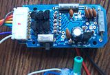
    So as most of you know, I am tackling a project which requires making a custom saber out of a ventress board. The board (after desoldering the switch) has 5 pins/pads and I am not quite sure how to make use of them when attaching my own switch. The pins on the board have 5 pads as follows:

    ON ~ On/Off ~ On/Off ~ On/Off ~ OFF

    You can find an image of the switch pad marking here:


    *** Update ***

    So as mentioned earlier, there are 5 pads under the switch once you remove it. When looking at the board with the mollex connector on the left, and the pads facing you... you need to wire pins 2 and 3
    ON ~ On/Off ~ On/Off ~ On/Off ~ OFF
    Last edited by Shadar Al'Niende; 09-18-2010 at 02:21 PM.
    Every time Tim ships an order... an angel gets its wings


    "Just get one and go nuts, that's how this hobby works. Get stuff. Go nuts. Period." ~FenderBender~

  2. #2

    Default

    Well if you hadn't destroyed your switch you could've metered it

    I would test wire it and then just play around with some wires to see what works.
    But ON and OFF sounds like the best idea to me

    Click here to learn all about me!
    The Shoutbox: The only place you can double post!
    Anybody who spells it Lightsabre is dyslexic
    "Yeah, if I had Skotts face I'd hit it too" ~ Fenderbender
    "You didn't buy a toy saber just to break it. You bought an economy sound card with a really complicated wrapping scheme." ~ Silver Serpent

  3. #3

    Default

    If you are lucky then the on/off could be wired to a clash or motion sensor so that if either the motion or clash were triggered the saber could activate, I've heard of this system before but I have never worked with this board before.
    Good luck on your build.
    My real and legal name is Rogue. Coincidence that i like starwars. Perhaps.

  4. #4

    Default

    1) Clash/Swing sensors are momentary and therefore wouldn't work in that application.
    2) Why would you want to do that?

    Click here to learn all about me!
    The Shoutbox: The only place you can double post!
    Anybody who spells it Lightsabre is dyslexic
    "Yeah, if I had Skotts face I'd hit it too" ~ Fenderbender
    "You didn't buy a toy saber just to break it. You bought an economy sound card with a really complicated wrapping scheme." ~ Silver Serpent

  5. #5
    Council Member
    Jedi Council Member
    Rhyen Skytracker's Avatar
    Join Date
    Feb 2009
    Location
    Covington, GA
    Posts
    2,550

    Default

    How many wires actually went to the switch? I know the MR Mace Windu had a 4 wire switch and used s DPDT switch but you could get it to work only using 3 wires and a SPDT switch. We really don't haven enough information yet.

    Live long and...I mean May the force be with you. http://saberconcepts.50.forumer.com/index.php

  6. #6

    Default

    The switch was a metal housing with each end attached to the On and Off pads. It had a small plastic switch that would "click" into two different positions, I am assuming using two On/Off pads and possibly either ON or OFF in conjunction. (basically a DPDT?)

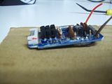
    You can see here what I am talking about. This image shows the ON and OFF on either side with a single On/Off for each of the 3 pads underneath, the On/Off is somewhat hidden by the switch:


    This image shows Pads I was talking about:


    Let me know what more you would like, i can take more pics of the board. From my knowledge of switches... which isn't much, my bet is that it is a DPDT switch... i just don't understand enough about how to wire that with my AV....
    Last edited by Shadar Al'Niende; 09-06-2010 at 03:09 PM.
    Every time Tim ships an order... an angel gets its wings


    "Just get one and go nuts, that's how this hobby works. Get stuff. Go nuts. Period." ~FenderBender~

  7. #7
    Council Member
    Jedi Council Member
    Rhyen Skytracker's Avatar
    Join Date
    Feb 2009
    Location
    Covington, GA
    Posts
    2,550

    Default

    What I would do it solder a wire to each pad and strip the other ends off. Touch them together one at a time to see what results you get. You may have to touch 2 together at a time to test too. That is how I was able to determine how to wire up the 4 wire switch on the Mace Windu board. http://forums.thecustomsabershop.com...ad.php?t=11171

    Live long and...I mean May the force be with you. http://saberconcepts.50.forumer.com/index.php

  8. #8

    Default

    I wouldn't be surprised if a couple of those holes in the board were simply to solder the switch onto the board, and may have nothing to do with activating the board....follow the traces from the holes(pads) and see where they go....if a hole has no trace, then you don't need it.

    Got a question? Start Here. Have you tried the Thread Index yet? Most questions can be answered there.

  9. #9

    Default

    Quote Originally Posted by Rhyen Skytracker View Post
    What I would do it solder a wire to each pad and strip the other ends off. Touch them together one at a time to see what results you get. You may have to touch 2 together at a time to test too. That is how I was able to determine how to wire up the 4 wire switch on the Mace Windu board. http://forums.thecustomsabershop.com...ad.php?t=11171
    Thanks for the tip on how to test it all out Rhyen!

    Quote Originally Posted by Jay-gon Jinn View Post
    I wouldn't be surprised if a couple of those holes in the board were simply to solder the switch onto the board...
    That was what i thought, since the switch was attached by the two outer pins. That would also only leave 3 pins which would make sense why there is only 3 annotations on the board (ON, OFF, and ON\OFF)

    Quote Originally Posted by Jay-gon Jinn View Post
    ...follow the traces from the holes(pads) and see where they go....if a hole has no trace, then you don't need it.
    On looking at the underside of the board, the pins 2 and 4 (1 2 3 4 5) have traces coming from them. The center pin looks like it might lead to a resistor on the top of the board but doesn't specifically LOOK like a trace. This leads me to believe that Pins 2 and 4 are the On and OFF and the center pin is the ON\OFF. I suppose when i get it wired up I will have to try pins 2 and 4 to see if that does the trick, then add the 3rd a'la Rhyen's Mace Board diagram!

    Thanks again guys!
    Every time Tim ships an order... an angel gets its wings


    "Just get one and go nuts, that's how this hobby works. Get stuff. Go nuts. Period." ~FenderBender~

  10. #10

    Default

    Keep us informed on what you find!

    Got a question? Start Here. Have you tried the Thread Index yet? Most questions can be answered there.

Bookmarks

Posting Permissions

  • You may not post new threads
  • You may not post replies
  • You may not post attachments
  • You may not edit your posts
  •