Page 1 of 11 1 2 3 ... LastLast
Results 1 to 10 of 110

Thread: Shadar's "Agony" (Crystal Chassis with Ventress FX board)

  1. #1

    Default Shadar's "Agony" (Crystal Chassis with Ventress FX board)

    Ok Folks, I caved.... (yes skott I know) I was going to wait until i had a gallery thread on this build before posting a Build Log... but I am just to excited and had to share!

    This build will be privy to a couple of firsts (to the best of my knowledge) in custom sabers. First being the use of a Ventress soundboard in a fully custom saber, not a conversion. (Since I know this will come up.... I am well aware of the controversy over this board. Some hate it, some love it. Through speaker placement and hilt resonance I hope to cure the "angry bees" and have quality, low toned, Sith sound without the monkey gong. now enough of that discussion...)

    Second being something I debuted the idea of back in November of last year.... A crystal chamber reveal using a clamp.

    To give you a little background, and to help you understand the reason behind the name for this saber, I will explain how it all started. There were a couple of design cues that I wanted in the next saber I built.


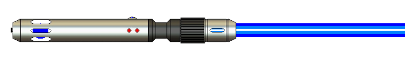
    I had been wanting to do the C4 design mentioned earlier which, As you can see from this initial render, meant a crystal chamber. I also wanted the Gear section below the Blade Holder, I had not seen this recently and truly loved the idea aesthetically. The saber began life as a Jedi saber (i have made 3 so far, all Jedi) but then later became a Sith design.

    The name Agony initially came about because no matter how I tried, i COULD NOT get the hilt below 14" using the Gear section and space for a crystal chamber, two design cues I was not willing to build the saber without. I personally prefer sabers to be 10-12" in length, anything over this feels too long and cumbersome to me. So I initially called this saber "Agony 14" in humorous reference to the agonizing i did, attempting to get everything i wanted to fit in anything under 15". The fact that it became a Sith saber and the back story later on, just fit perfectly.

    The build has presented MANY challenges in the time that i have designed, and re-designed it. Adding to the reference of Agony. Soon the Saber included a PLI, another thing i simply could not live without.


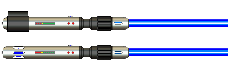
    Here you can see the Clamp reveal. Thanks goes to Skottsaber, and many others who have been my confidants on this build, and helped me hammer things out. Doing a Crystal Chamber presented me with a unique opportunity to design and implement a chassis! In designing the chassis, I realized that having the crystal chamber near the blade holder allowed for a few more easily executed parts of the build, wiring being one of them. This was about the time that the saber evolved into a Sith saber.


    You can see from this render that a few things changed, namely the color, positioning of the chassis, crystal chamber and switch placement, with an addition of a Shroud piece. The shroud piece has yet to be decided upon, chrome or brass, and what design to put in it. (or if to do a completely different shroud all together. ) You will also see some rough approximations for measurements, meant to help me design the electronics. At the present time, the Custom work on the Blade holder (the milled slots) may not happen, but I am gunning for it ; It all depends on funding and timing. Skott you have my paypal address )

    Now that you understand a little more about the background, (thanks for those that are still reading...)

    ON TO THE BUILD LOG PICS!
    (to help with the already long load for this thread, and due to the fact that not all images are within forum guidelines, i will make these click-able thumbnails.)

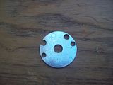
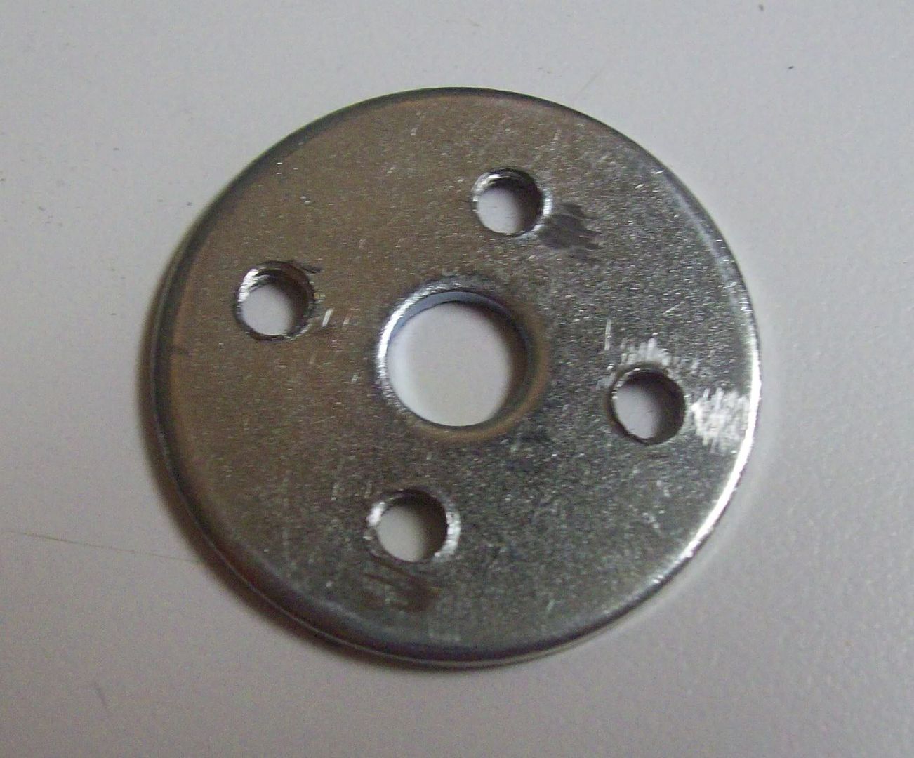
    Firstly I had designed the internal Chassis system using 4 threaded rods to hold the batteries, soundboard, and PLI. I started out drilling a typical 1.25" OD steel Fender Washer to accept my 8/32 threaded rods.


    I had previously purchased some brass tubing when making my crystal chamber proof of concept (found here) and planed on using this tubing in my build for Agony. A lot of people use rod such as this to cover the threaded rod, to make things look more sleek.

    Here you can see the tubing on the rod, along with the knurled nut used for the Crystal Chamber.


    This was done early on, before more problems came up and parts were even in hand. The Chassis system became redesigned due to space limitations. Shortly I was able to purchase some initial parts for the internals and Chassis, and was able to really measure things out and see them visually.


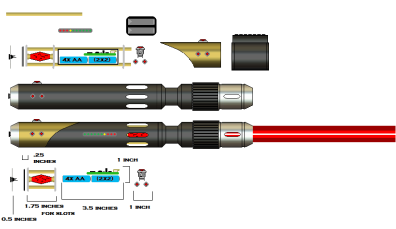
    I am going to be using 4 AAA NiMH to power this build, and initially wanted to place them in a 4x configuration so as to save on length...


    This ended up not working due to space constraints of the chassis and so I will be soldering them in a 2x2 configuration as shown in the render above.

    Setting up the chassis the way I did, I could not connect the rods for the chassis to the pommel insert, and I did not want to attach it to the Pommel since i would have to pre-twist my wires for the recharge port that will be in the pommel. In order to do this, i needed a way to keep the pommel insert from "receding" back into the hilt. Especially since i was going to be plugging and un-plugging the kill key. I was able to engineer a solution!

    I screwed the recharge port into the insert and measured everything, I would need to clip the port a bit, but everything should fit. That left me with the problem of getting 6 wires (4 for the port and 2 for the speaker) between the OD of the speaker and the inner wall of the Pommel. Any of you who have used a speaker anywhere like this know how difficult this can be, UNLESS... you modify the speaker....

    You can see (may have to look closely at the full resolution photo) that I put 3 notches in the OD of the speaker. There is enough space for exactly 2, 26 gauge wires to sit side by side in each of the notches.


    Next I clipped down the tabs on the port and used my sanding wheel to smooth them out (jagged metal + speaker + wires = BAD! )


    I Placed the insert into the pommel with port screwed in, and then placed my speaker on top for a test fit. There is just enough room for wires between the port and speaekr!


    I could not sleep one night and had sabers on the brain I came downstairs and started fiddling with my parts. (alright you guys, no wisecracks ) i knew the batteries in a 2x2 configuration would barely fit the board on top between my two threaded rods. How the HECK was I going to get my PLI secured with it? In frustration I set my PLI down against the batteries and rested my chin in my hands... then, blankly staring at the PLI inspiration struck! I quickly got out my measuring tape and measured the width of my batteries + the PLI. 1.243" !!!

    It will JUST fit, with the heatshrink i'm using.


    As you can see from the image above, i briefly played around with the idea of using some of the chrome housed accent LED's for the crystal mounts as I had seen some do. (I have since ordered a couple Makototsai v2 red LED's to use with the knurled nuts instead.)


    The board and batteries JUST fit between the rods, I may not be able to use the brass tubing without modification, its that tight....


    So I had my Washers somewhat drilled, at least for the main chassis section, but I needed to drill holes for my "switch section". As you can see from earlier pictures, i had my two rods on the "top" and "bottom" of my chassis, this would interfere with my AV switch, so I would have to run them differently. I first planned on running them on the two "sides" Like i was planning for my crystal chamber, but realized this would interfere with my accent LED's. To remedy this i drilled out a couple holes a little higher on the washer, in order to "nestle" the switch in between them. This would also serve to hold the chassis in place from spinning in the saber.

    And then....

    DISASTER STRIKES!!!

    I miss-mark my punch for the drill bit...


    You can see the idea i was going for below


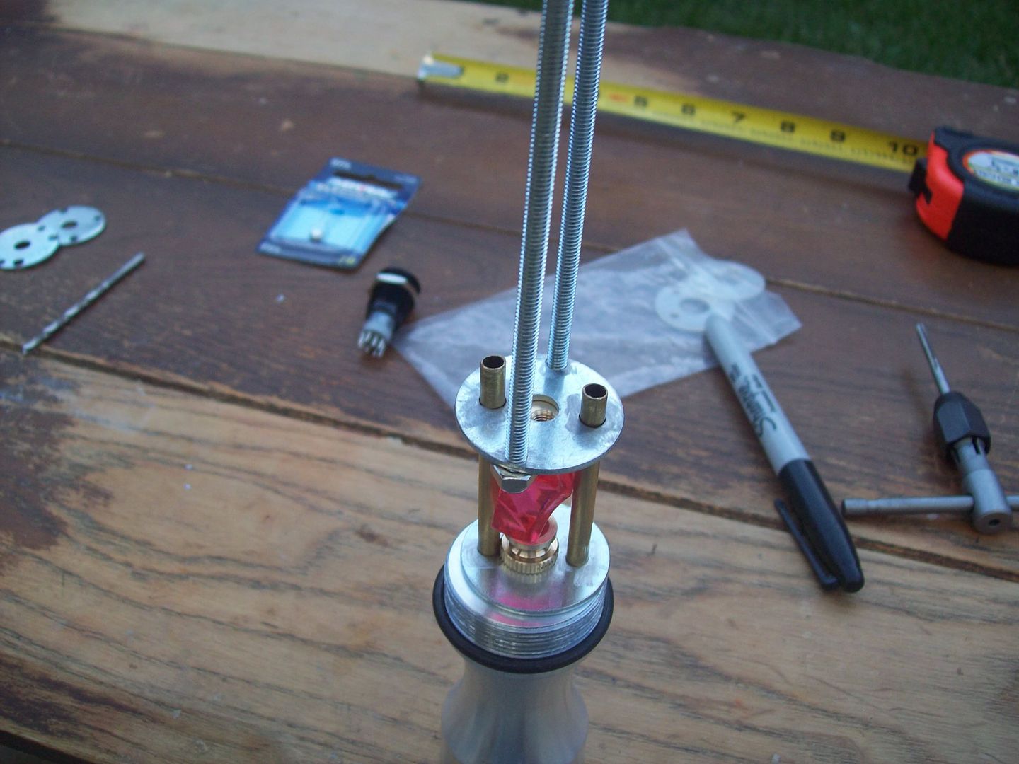
    With all of this out of the way, i started fresh today, with some new washers. I started completely over. After everything was drilled and tapped, I put it all together!

    You can see here my idea for the Crystal Chamber


    As well as the main chassis section (the rods will be trimmed later)


    Here is cross view of how the switch will sit as mentioned earlier


    And a couple more shots


    Finally, I had to make sure that the two rods that held the crystal chamber section would be close enough together to allow my Main LED wires to pass through the choke section. I had a choke 3 sitting around from another build and tested to see how it would fit with the ID

    Success!


    The choke will sit against the "front" washer of the chassis, like this:


    so it is important that everything be snug.


    This is where I am at so far. I should receive my 8" DF and Choke from Tim on Monday, which will allow me to test fit everything in order to get measurements exact. At that point I will be able to start plotting everything out and begin the wiring of this monster I want the accent led's, PLI, and AV to come on when the kill plug is pulled, and the crystal to sync with the main LED, so I will have to wire in the crystal chamber off a neg lead on the board, and the other accents straight off the pack. I am concerned about loosing current this way (read: run time) but have yet to decide how this will occur.

    A couple extra points to make note of:

    I noticed in one of Makototsai's threads that he uses clear packing tape for heatshrink, I picked up a roll to use at my local hardware store and will test it to see how heatshrink-able it is (should only be lightly so) and how feasible it is thickness-wise. Otherwise I will order some online. (Note, this is only for the board and batteries, all wires will be heatshrunk with normal materials)

    Also, my MPP clamp for this build has to be shipped next week so should arrive by the weekend. I still have one more order to make when Blade holders come back in stock and then that should finish it all up.

    Thanks again to Tim for this site and AMAZING customer experience, and Skottsaber for the HOURS of AGONY! Thanks to raf who did an amazing render of my saber which will be included in the Gallery thread as well, and thank you to all those who are following this. I am more excited that words can describe. Trust me, look at the length of this post!!!

    Stay tuned... more to follow!
    Last edited by Shadar Al'Niende; 08-29-2010 at 12:56 PM.
    Every time Tim ships an order... an angel gets its wings


    "Just get one and go nuts, that's how this hobby works. Get stuff. Go nuts. Period." ~FenderBender~

  2. #2
    Jedi Padawan Ronan's Avatar
    Join Date
    Jul 2010
    Location
    Montreal, QC
    Posts
    529

    Default

    Sweet! Good inspiration for me to get started!

    Sent you a PM mate

  3. #3

    Default

    Now that's the longest post I've ever seen!

    Your doing good so far..

    (If I have some extra time I will HAVE TO re-do your render because right after that I became a billion times better, so...)

  4. #4

    Default

    Skottsaber is now inspired....

    *Goes off to finish the backstory*

    Click here to learn all about me!
    The Shoutbox: The only place you can double post!
    Anybody who spells it Lightsabre is dyslexic
    "Yeah, if I had Skotts face I'd hit it too" ~ Fenderbender
    "You didn't buy a toy saber just to break it. You bought an economy sound card with a really complicated wrapping scheme." ~ Silver Serpent

  5. #5

    Default

    Ok folks, another update. Got my DF and my Choke from Tim today along with a few other components. I had Tim heavily modify the 8" Double Female part, (ok so maybe not so heavily, but it seemed like a lot to me...) I figured I would show off what I had him do.

    In keeping with the design posted earlier, I had him drill a 16mm switch hole for an Illuminated AV, I will be using a Black Red Dot AV sold here in the store, and two holes for the accompanying Accent LED's.


    To save on space, i opted to have Tim cut the Crystal Chamber cutouts directly into the Double Female, so that I did not have to use an adapter between it and the choke. While I was at it, I figured I would have him Chamfer the slots to give it a little something extra.


    I also opted to have him put a cutout for the PLI, directly behind the Crystal Chamber cutouts, you will see why in a moment.


    Another quick shot of the Crystal Chamber, because it looks so amazing


    So now that I had the parts in hand, I could really start measuring things out, seeing how they fit, and definitively start constructing my chassis. First thing first I test fit my washers.


    They don't fit perfectly, so I took my dremel and sanding wheel to the OD, BARELY shaving off a bit at time. I knew that my Crystal was not long enough to occupy the entire 2" chamber I had planned, and so I measured my Knurled nuts to see if it would make up the difference... I was roughly .5" short...


    So, I cut two .25" sections of brass tubing off of the 3 foot rod that i purchased at a local RC hobby shop (for 6 bucks might i add ) and used them as spacers for my crystal. I Don't have epoxy (i reeeeealy need to get some) and so decided to solder my components together. It was a bit of an exercise in frustration, but eventually I got it all together, and am fairly satisfied with the result. If I had to do it over again, I would use a 2 part epoxy to solidify the parts a bit more.


    After putting together the actual crystal chamber part of the chassis, I test fit it in the hilt. Due to some crooked drilling on my part my washers were not COMPLETELY parallel, and so it took some more light dremeling on the OD to get it to slide in and out of the hilt without "sticking."


    While I had my parts on the "bench" (read: kitchen counter ) I wanted to check how far in the Accent LED's sat. I had heard that you could pull the LED out of the "plug" and screw in the insert, then simply pull the wires through the plug and wire it up snapping the accent led back into the insert. I could not easily figure out how to do this. The Accent LED seems stuck although there is SOME wiggle to it....

    Looks nice and pretty so far!


    I checked the internal spacing:


    Like I had suspected, the leads will need to be clipped, but with the planned spacing, the AV sits right between the two Accent LED's and it shouldn't be too big of a deal to get it all in there.

    Here is a quick shot to show the spacing on the PLI cutout that Tim did for me, it will fit PERFECTLY! All I have to do is line it up when attaching it to the chassis.


    Remember how I mentioned earlier that I had Tim cut the PLI slot right behind the Crystal Chamber? Here is Why:


    Like I previously mentioned, the PLI will sit against the "side" of the batteries and press up against the ID of the hilt. I will mount the PLI on the "front" set of batteries, or the ones nearest the blade holder. Here is a closer shot of the battery board combo


    I also wanted to show the wiring diagram as I have it planned. I have hesitated to share it since it is not clear in the least bit, but figured I would post it here in case someone had feedback on it. (P.S. Don't mind the duck, its a clash sensor...)


    That is all the build pics for tonight, I am still waiting for the Blade Holders to come back in stock before placing my final order. (as of composing this post they are still out of stock) I have decided a few things since my last post that I will make note of here.

    The Blade holder will NOT have milled slots similar to the Crystal Chamber. This is due to a number of reasons, funds being one of them and the design overall being another. Also, I will leave the shroud Chrome to match the rest of the "silver" on the outer hilt and to allow the brass in the Crystal Chamber to "pop" more.

    Thanks for reading! I am hoping to have more updates in the next day or two as time permits. I would like to cut and position the tubing for the "switch" section of the chassis to make sure it all lines up, and possibly work on the custom battery pack and/or begin some wiring work.

    Stay tuned....
    Last edited by Shadar Al'Niende; 08-30-2010 at 08:56 PM.
    Every time Tim ships an order... an angel gets its wings


    "Just get one and go nuts, that's how this hobby works. Get stuff. Go nuts. Period." ~FenderBender~

  6. #6

    Default

    Pretty cool build. I look forward to seeing it complete.

    http://s6.photobucket.com/albums/y23...0Saber%20Hilts

    From Wikipedia: "Internet Explorer slows down GIFs if the framerate is 20 frames per second or higher and Microsoft reports that Google Chrome and Safari also slow down some GIF animations."

  7. #7

  8. #8

    Default

    Oh, those slots look awesome! I had no idea Tim could do that. I will have to talk to him about an upcoming project... cause that is EXACTLY what I need!

    CordaroyFog: you know, its really mean to set the bar that high.

  9. #9

    Default

    custom CNC milling work is now available

    I think there is a thread/gallery on customized MSH parts to check out if you wanted.

  10. #10

    Default

    Ok, so I promised an update tonight if time permitted, and it did! My biggest worry going in tonight, was the switch section of the chassis. I realized When I was test fitting, that the rods might not have been done symmetrically with the rest of the chassis. This would throw EVERYTHING off as its all held in place (as stated) by the AV between the two brass rods.

    So I measured everything out, cut my brass tubing to fit, tested, re-cut, re-fit and finally did a full chassis test fit in the hilt.

    Here is a shot of the chassis outside the hilt


    Inside the hilt from the Blade Holder end


    Inside the hilt from the Pommel end


    A couple of shots of the rods inside the hilt


    It looked ok, so I stuck the AV in to test fit....


    IT FIT! and the chassis looked great! Here is a shot of the switch section with no Pommel end washer:


    Here is a short test video showing the AV in place, along with the Accent LED's (don't mind my son playing in the backround. I thought i had muffled the camera mic well enough since he wasn't in bed quite yet )


    Now that the chassis is built, I needed to start on the internals. I have never done a custom battery pack before, and wanted to do so in this saber. I was not prepared for the frustration of doing a custom battery pack. even after sanding the surfaces to be soldered, I STILL had difficulty. For any of you out there planning on doing this, let me share with you what works and what doesn't.

    It took a bit of heating to get the solder to do anything but stick to the iron and come right off, since that was the hottest piece of metal. Once I heated the surface sufficiently, the solder started to flow. (I was afraid of overheating my batteries... truth be told they got a bit warm while soldering them.) You MUST sand the tips lightly to give the solder something to grab on to. I tried soldering the batteries directly together... this did NOT work. What DID work, was pre-tinning so to speak, the + and - ends of the batteries, and using a small bit of wire (also pre-tinned) to connect the two battery surfaces. pictures are worth a thousand words so....


    After soldering them up into a pack, I checked them with my Multimeter to make sure that i was getting sufficient Voltage and that my solder joints were ok. (fighting with them i wondered if i had created a bad connection in one spot)

    With my leads touching the open ends of the circuit (by the way it is really hard to get that setup so it stays that way and you can take good pictures)


    I checked my Multimeter


    Here is a closeup so you can see the voltage, 5.15! YAY! (this is a 4.8v pack so these are giving a good intital charge.)


    Next I wanted to work on de-soldering the switch leads from the board. This was probably the most difficult and frustrating time of my night.... If I could take one thing away from this experience (since i feel that anything that brings that much pain also in opposition gives you that great of a lesson...) It would be that a solder braid (or "wick") is 100x better than a solder sucker.

    You can see here the 5 target pins so to speak. (PS if anyone knows which of the pads need to be soldered to for a switch let me know. It has an On, an OFF, and 3 On/Off pads)


    I de-soldered most of the switch but it refused to come out. So, I ended up (with my lovely wife's help) Prying most of the switch components off the board leaving only the pins. I was careful not to damage the board whilst doing this since it would be quite the pain to acquire a new one

    Here you can see what was left of the switch components


    Here you can see the pads now bare of pins on the "top" side of the board


    Finally I figured I would add a "bonus" pic! I have finally worn through my first sanding drum


    I am not sure what else I will be able to get done in the next day or two. I would like to start wiring everything up but want to wait on a few more parts from my final order. Hopefully the Blade holders will come back in stock tomorrow and I can get my stuff by the weekend!

    Stay tuned....
    Every time Tim ships an order... an angel gets its wings


    "Just get one and go nuts, that's how this hobby works. Get stuff. Go nuts. Period." ~FenderBender~

Bookmarks

Posting Permissions

  • You may not post new threads
  • You may not post replies
  • You may not post attachments
  • You may not edit your posts
  •