Page 1 of 2 1 2 LastLast
Results 1 to 10 of 14

Thread: Definitive Diagram for illuminated switch/recharge port/MR board?

  1. #1

    Default Definitive Diagram for illuminated switch/recharge port/MR board?

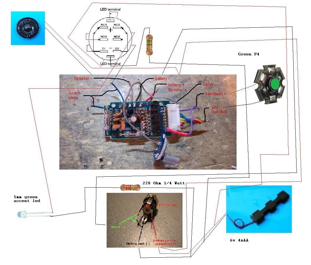
    I am going crazy trying to find a wiring schematic that shows how to set up a MR board with a recharge port AND an illuminated switch. I've found several different versions but they don't seem to be the same and some are really hard to decipher. Can anyone point me in the right direction?

    I've got the recharge port wiring down, but once I add the illuminated switch to the equation I get a bit....lost.
    Jedi Ronin. No Master, save the Force.

  2. #2
    Jedi Council Member cardcollector's Avatar
    Join Date
    Jan 2009
    Location
    I am A proud American.
    Posts
    2,567
    Blog Entries
    3

    Default

    Well, The illuminated switch is just like an extra accent LED.

    and then the switch is wired to the switch leads...
    Got a Question? There's a thread for that...
    ~Do what you can, with what you have, where you are.~Teddy Roosevelt

    SollusVir everywhere else... FXsabers, Youtube, etc...

  3. #3

    Default

    All you need to do is run a wire from one of the negatives on the board with the appropriate resistor and then just back to the pos.

    Click here to learn all about me!
    The Shoutbox: The only place you can double post!
    Anybody who spells it Lightsabre is dyslexic
    "Yeah, if I had Skotts face I'd hit it too" ~ Fenderbender
    "You didn't buy a toy saber just to break it. You bought an economy sound card with a really complicated wrapping scheme." ~ Silver Serpent

  4. #4

    Default

    UGH...talk about me making this harder then it is! Thanks guys! I'll give it a try when I next have free time.
    Jedi Ronin. No Master, save the Force.

  5. #5

    Default

    Every time Tim ships an order... an angel gets its wings


    "Just get one and go nuts, that's how this hobby works. Get stuff. Go nuts. Period." ~FenderBender~

  6. #6

    Default

    Shadar,

    Thanks, I'd seen that, but found it too hard to follow. All the lines leading all over! Most likely that is a reflection on ME and not YOU. You should see the diagram I tried to make for myself. It looks like someone gave a monkey access to photoshop.
    Jedi Ronin. No Master, save the Force.

  7. #7

    Default

    Ha ha no worries, even I had a hard time following that one.... And i made it

    I usually just follow one wire from board to component and make my own diagram....
    Every time Tim ships an order... an angel gets its wings


    "Just get one and go nuts, that's how this hobby works. Get stuff. Go nuts. Period." ~FenderBender~

  8. #8

    Default

    I think I've got it now and will try this weekend.

    Just to confirm one thing - I need a 68 Ohm 1/4 Watt resistor on the green illuminated switch if I am using 4.8 volts, correct? Does not matter if I place that on + or - ?
    Jedi Ronin. No Master, save the Force.

  9. #9

    Default

    technically no, it does not matter but since electricity flows from neg to pos i always put it on the neg
    Every time Tim ships an order... an angel gets its wings


    "Just get one and go nuts, that's how this hobby works. Get stuff. Go nuts. Period." ~FenderBender~

  10. #10

    Default

    Quote Originally Posted by Shadar Al'Niende View Post
    technically no, it does not matter but since electricity flows from neg to pos i always put it on the neg
    doesnt electricity ply positive to negative? its just the electrons flowing backward?

Bookmarks

Posting Permissions

  • You may not post new threads
  • You may not post replies
  • You may not post attachments
  • You may not edit your posts
  •