


So, since FX-Sabers is down (again....) I thought I'd post a build topic here for a change!
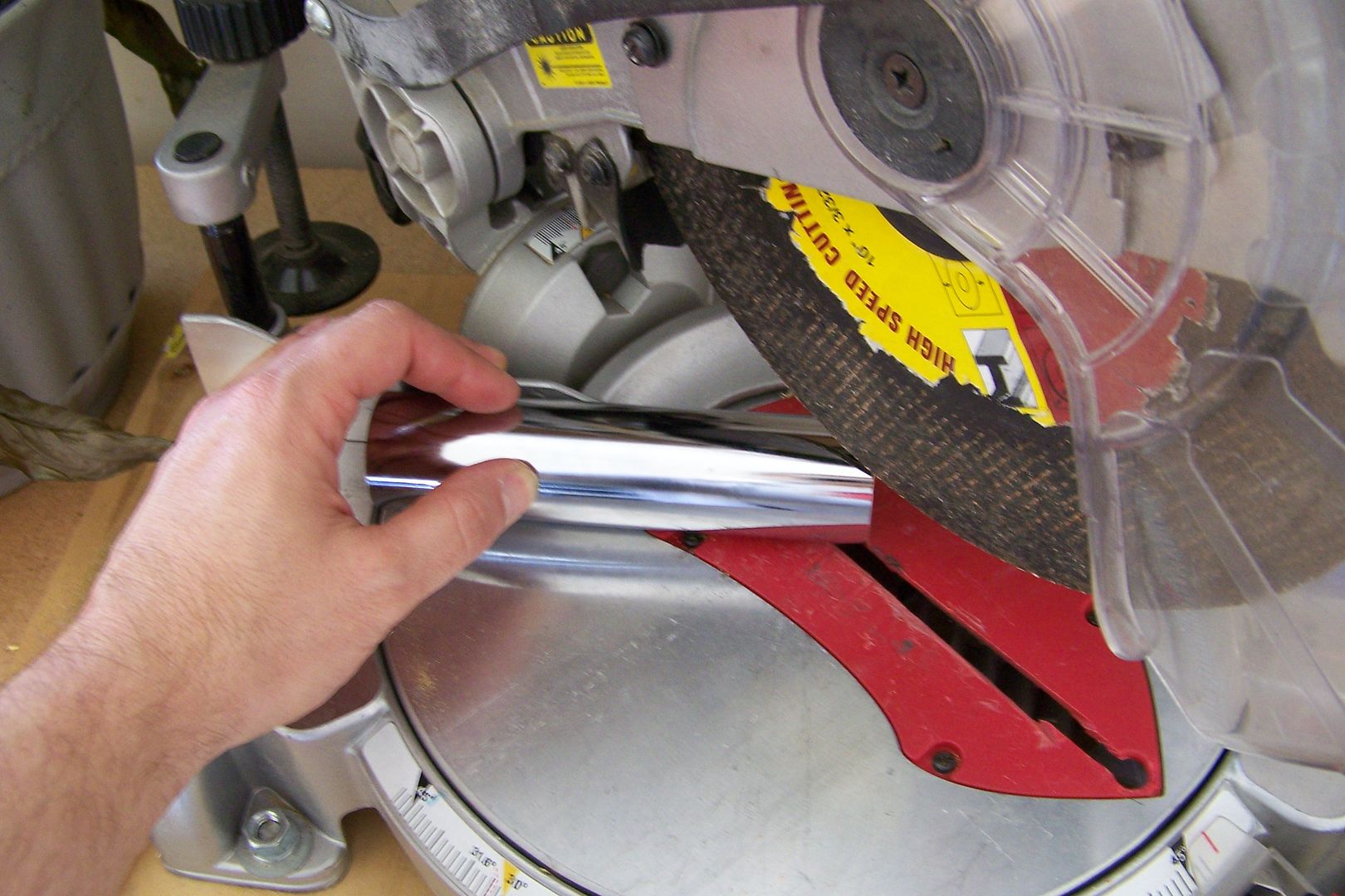
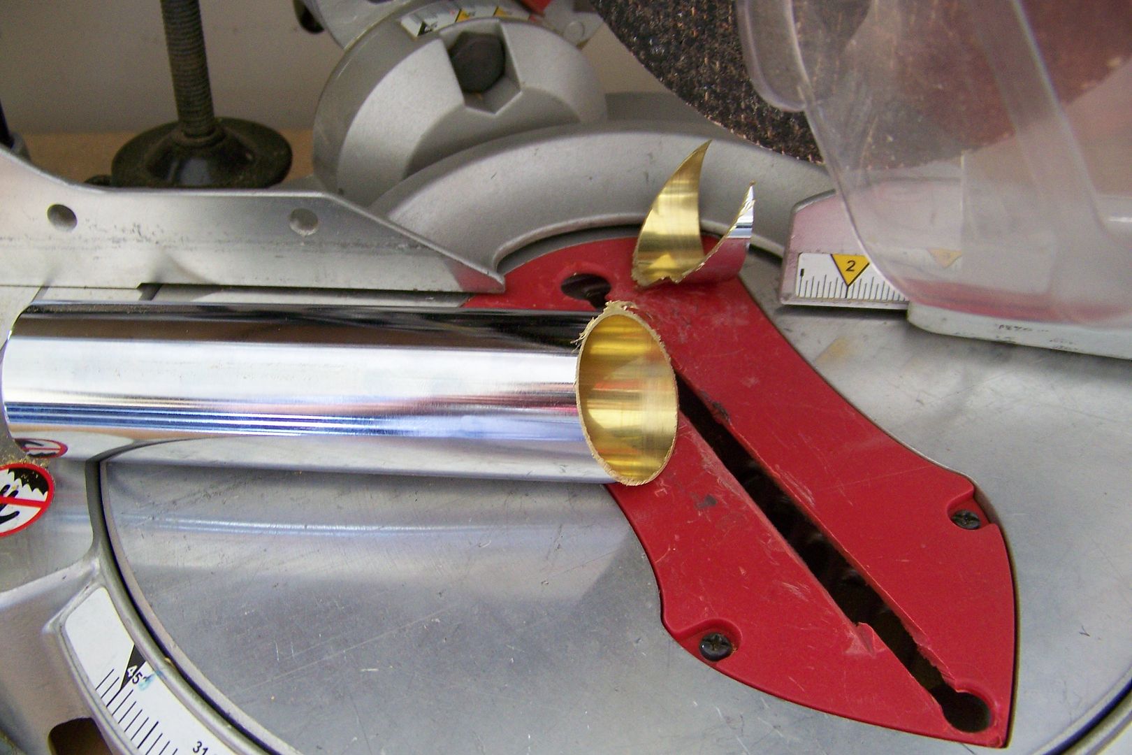
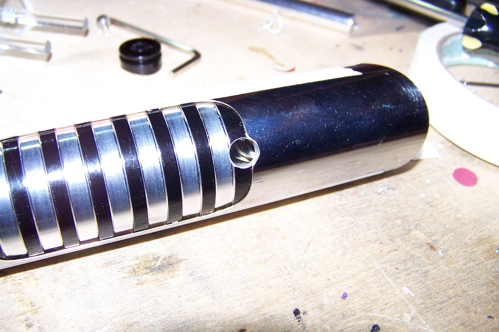
This saber will be using a customized 5" double threaded female adapter, and a couple of custom powder coated parts done by Tim.
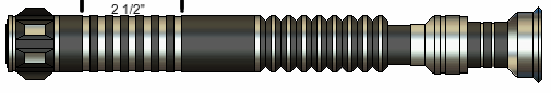
Here's the render:
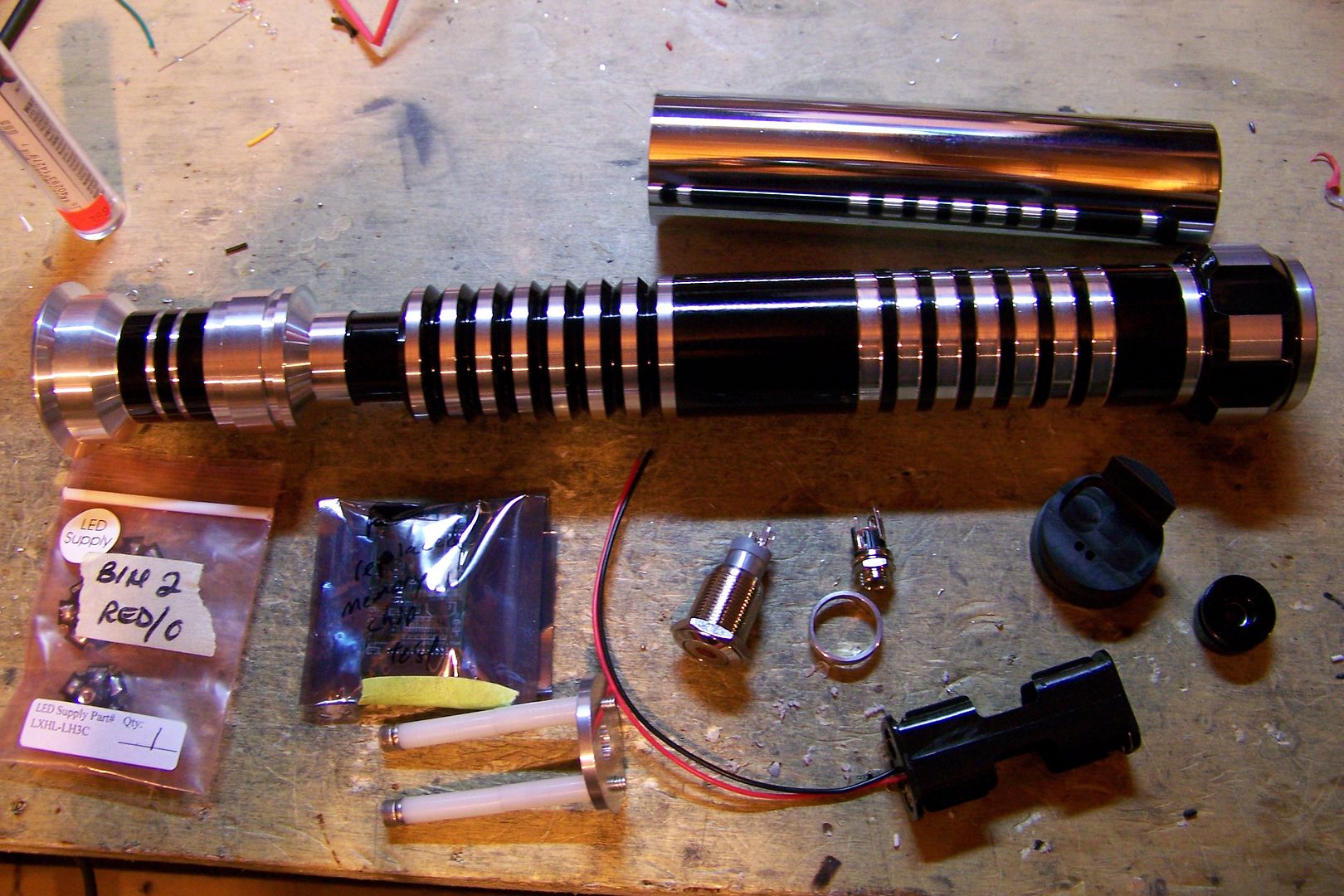
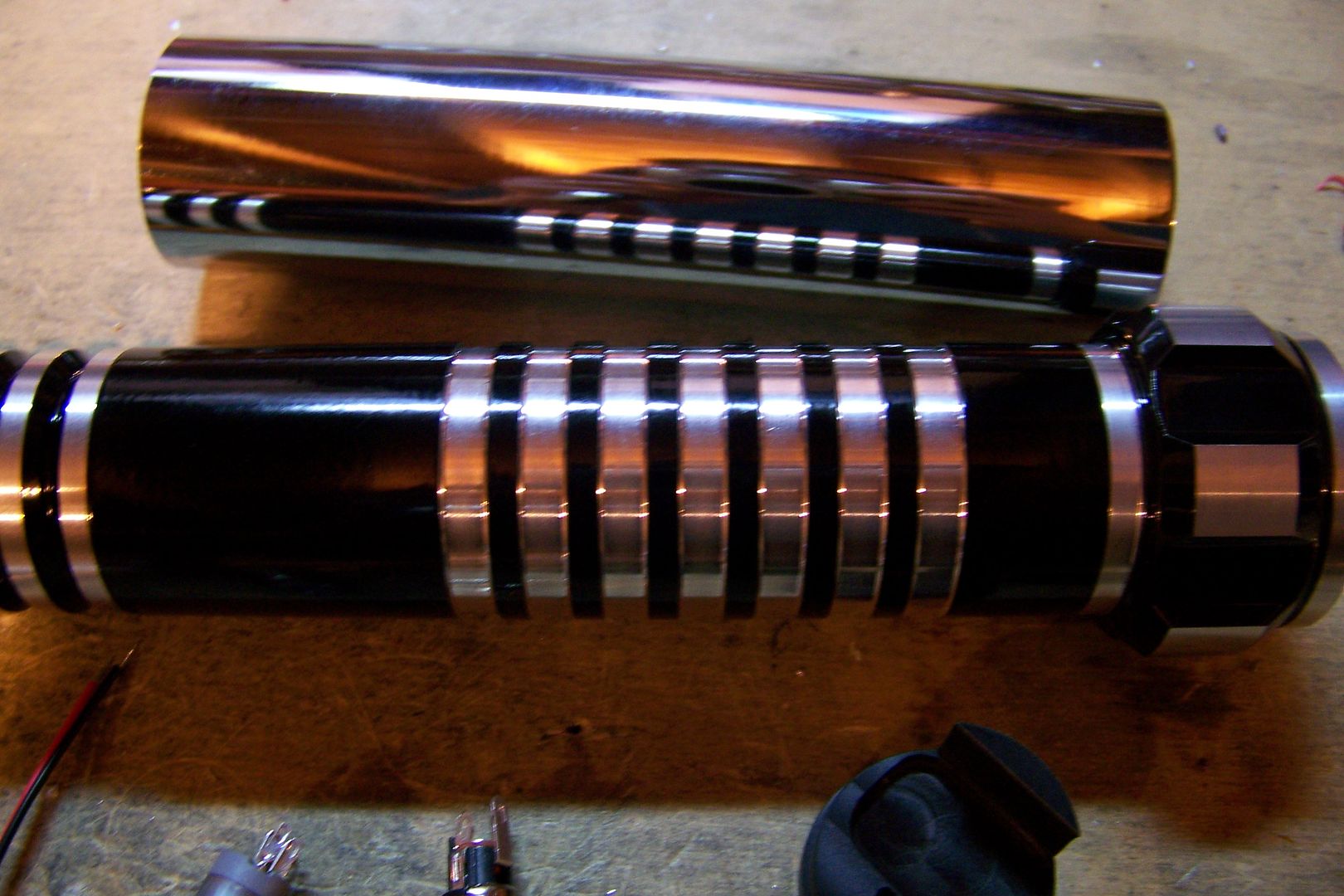
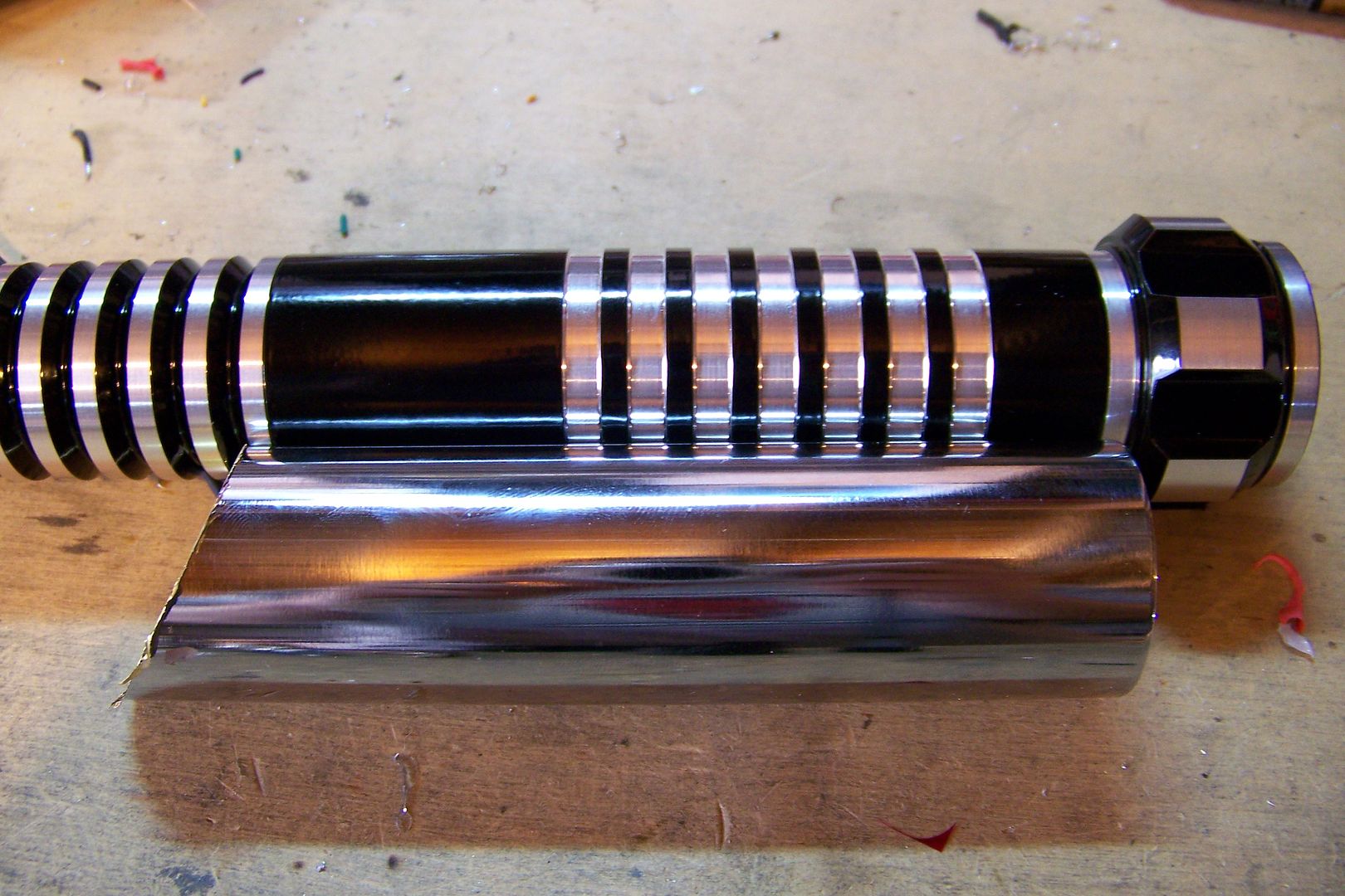
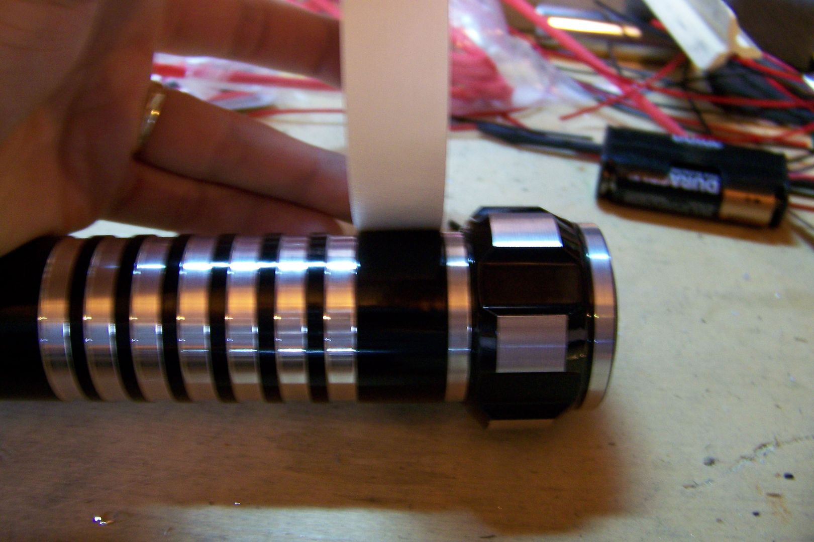
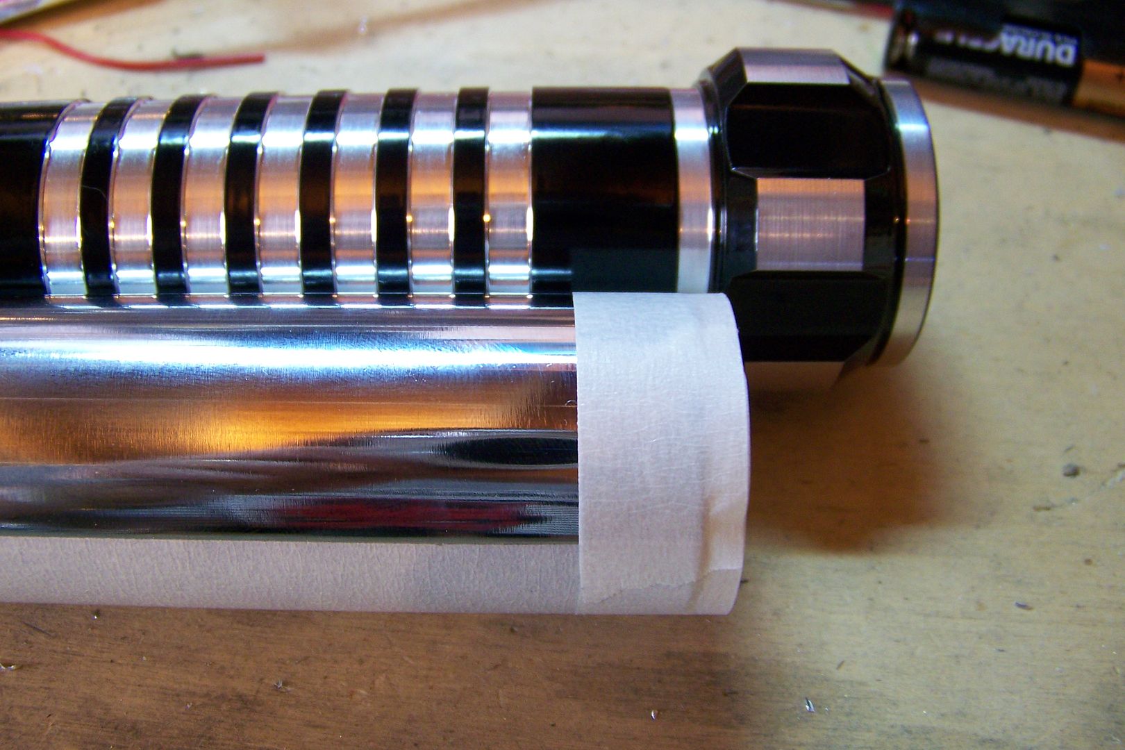
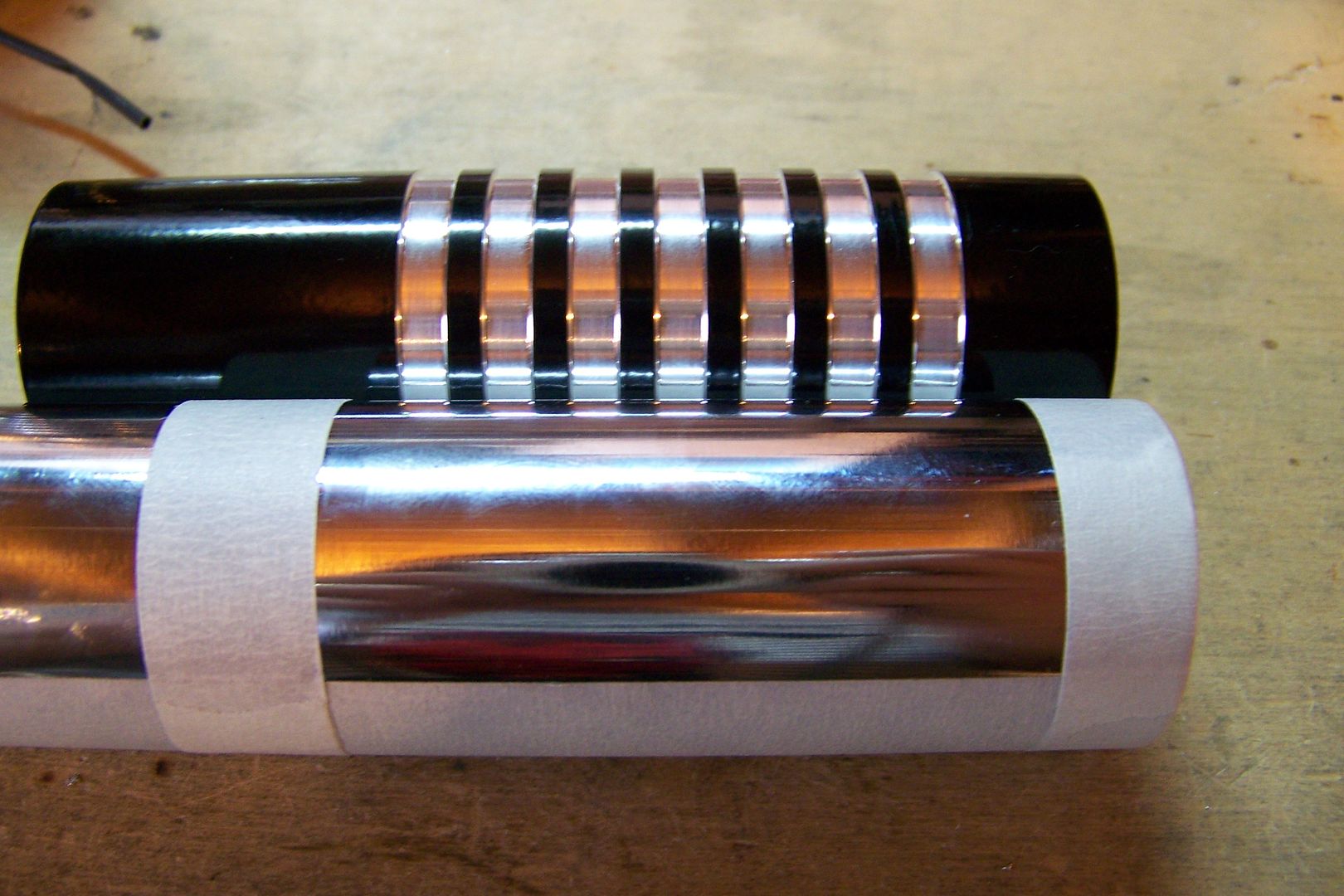
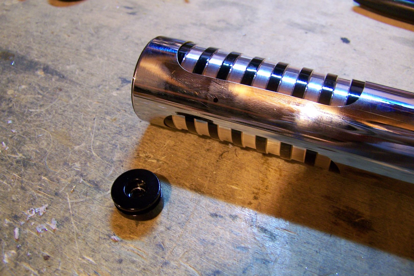
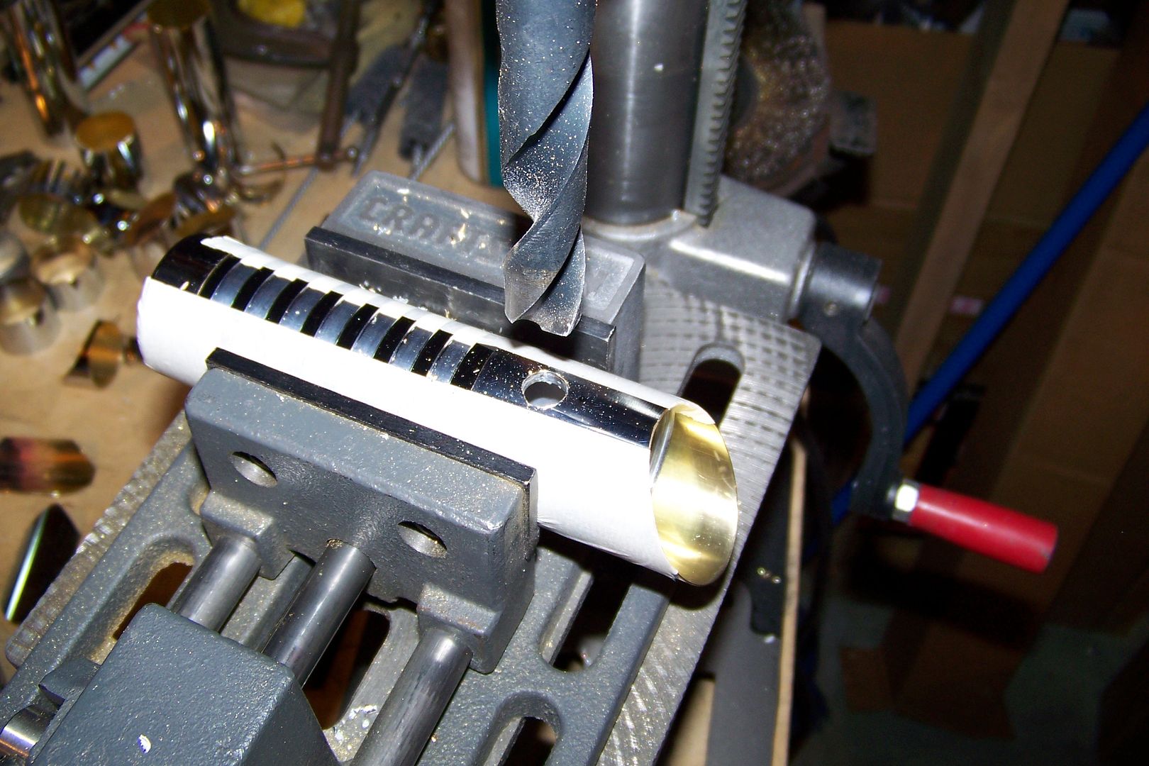
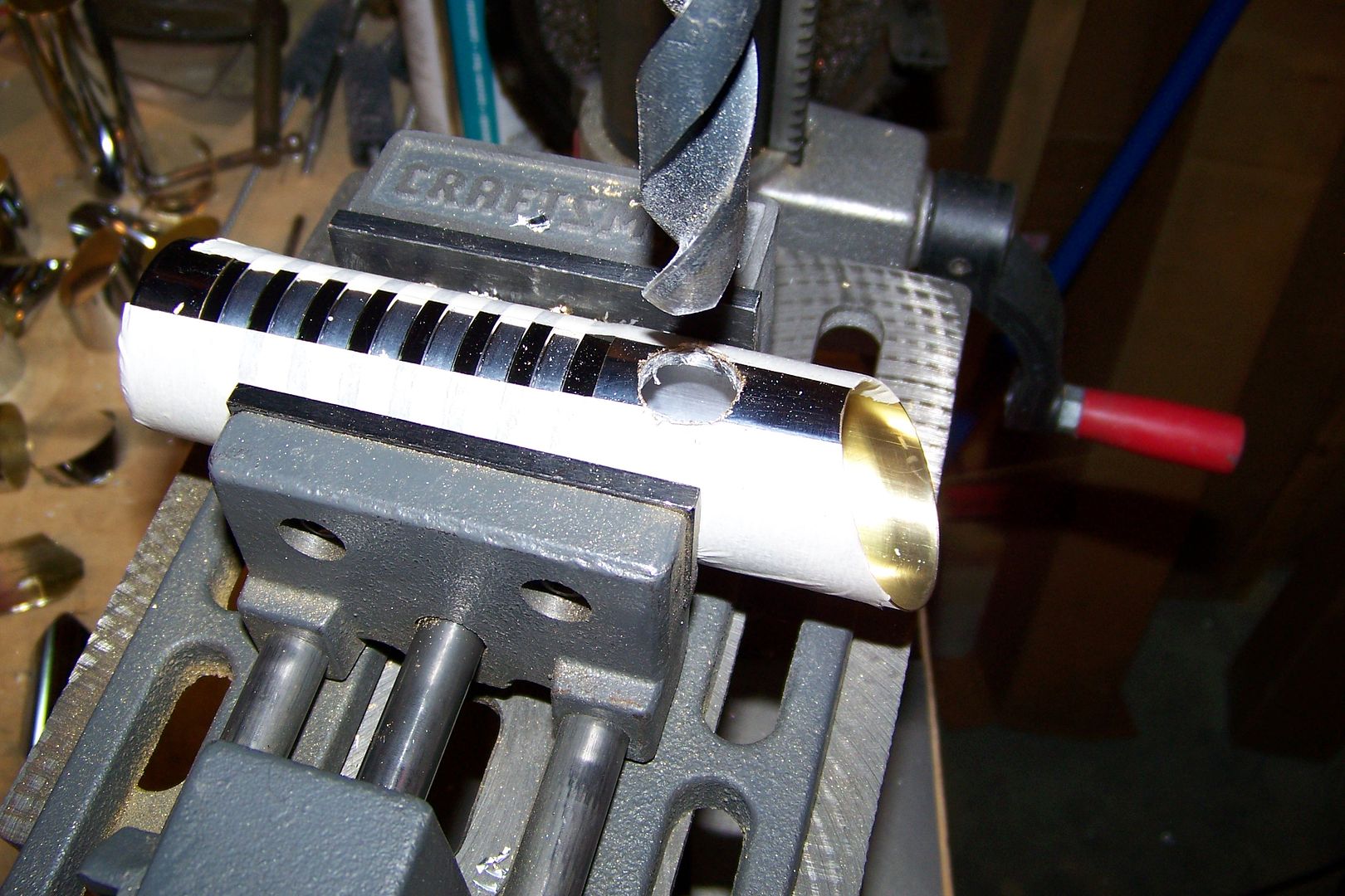
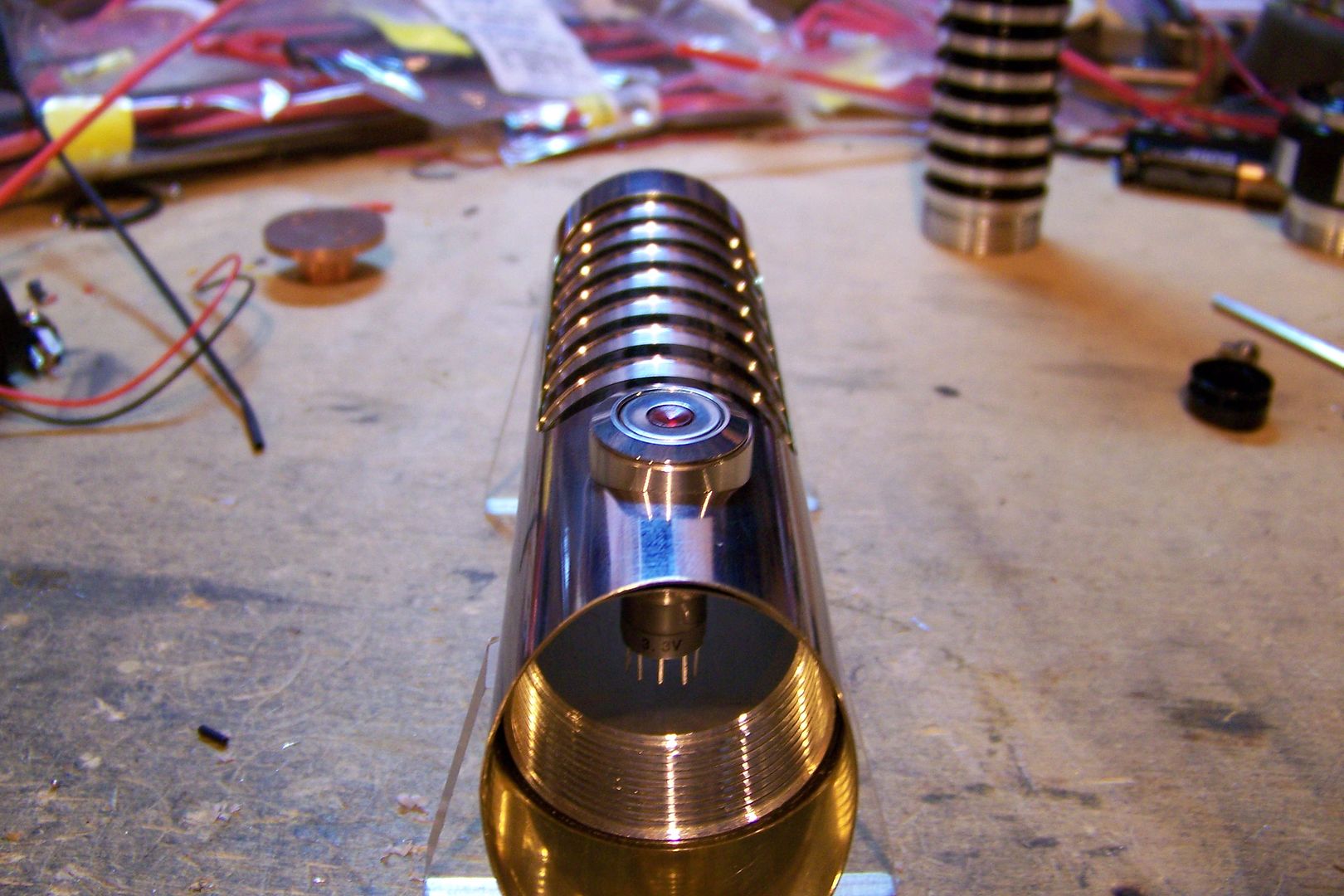
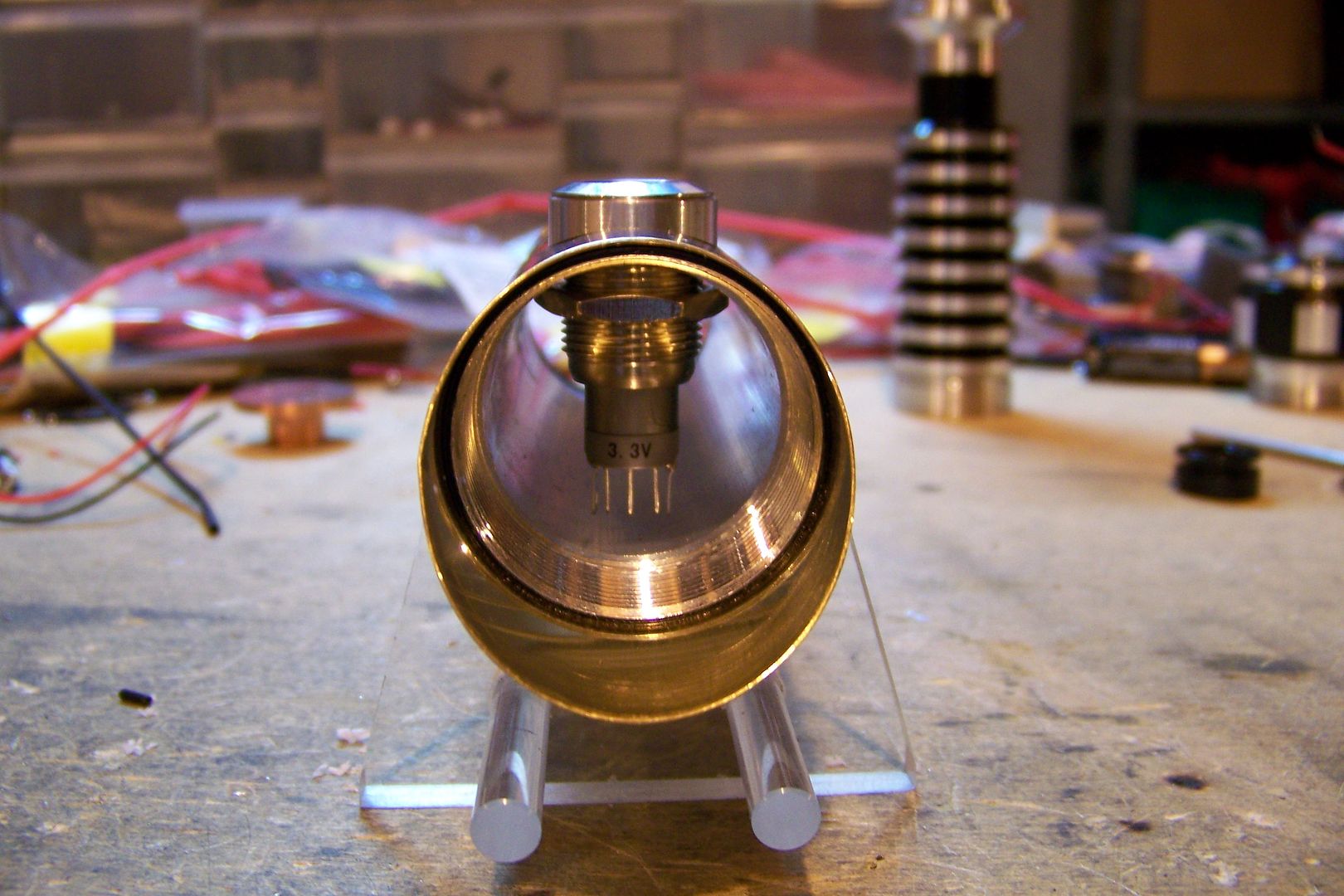
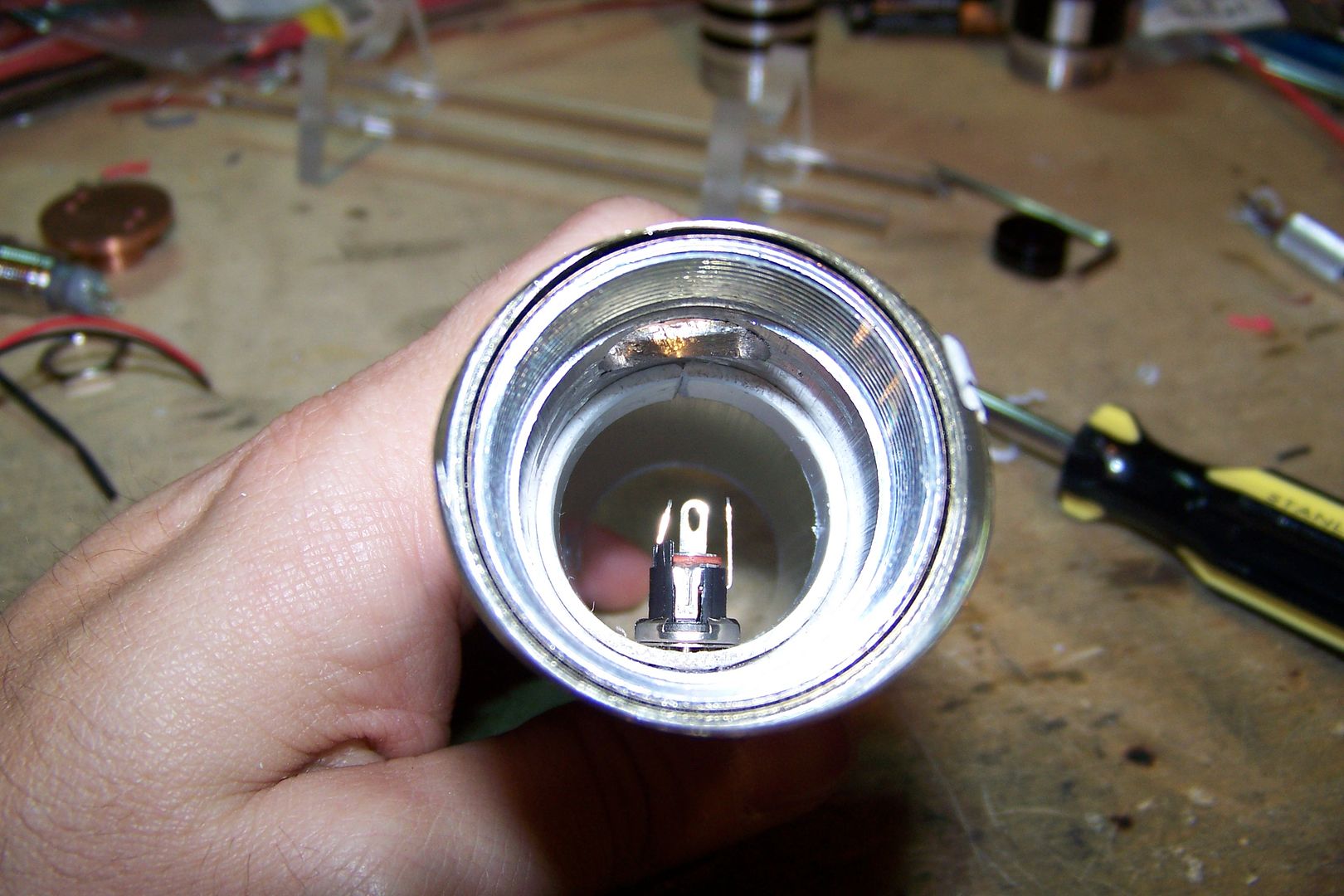
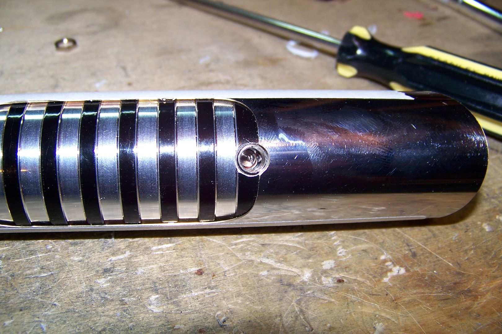
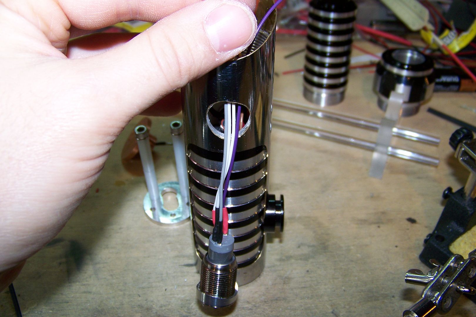
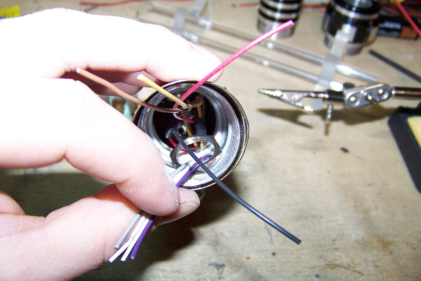
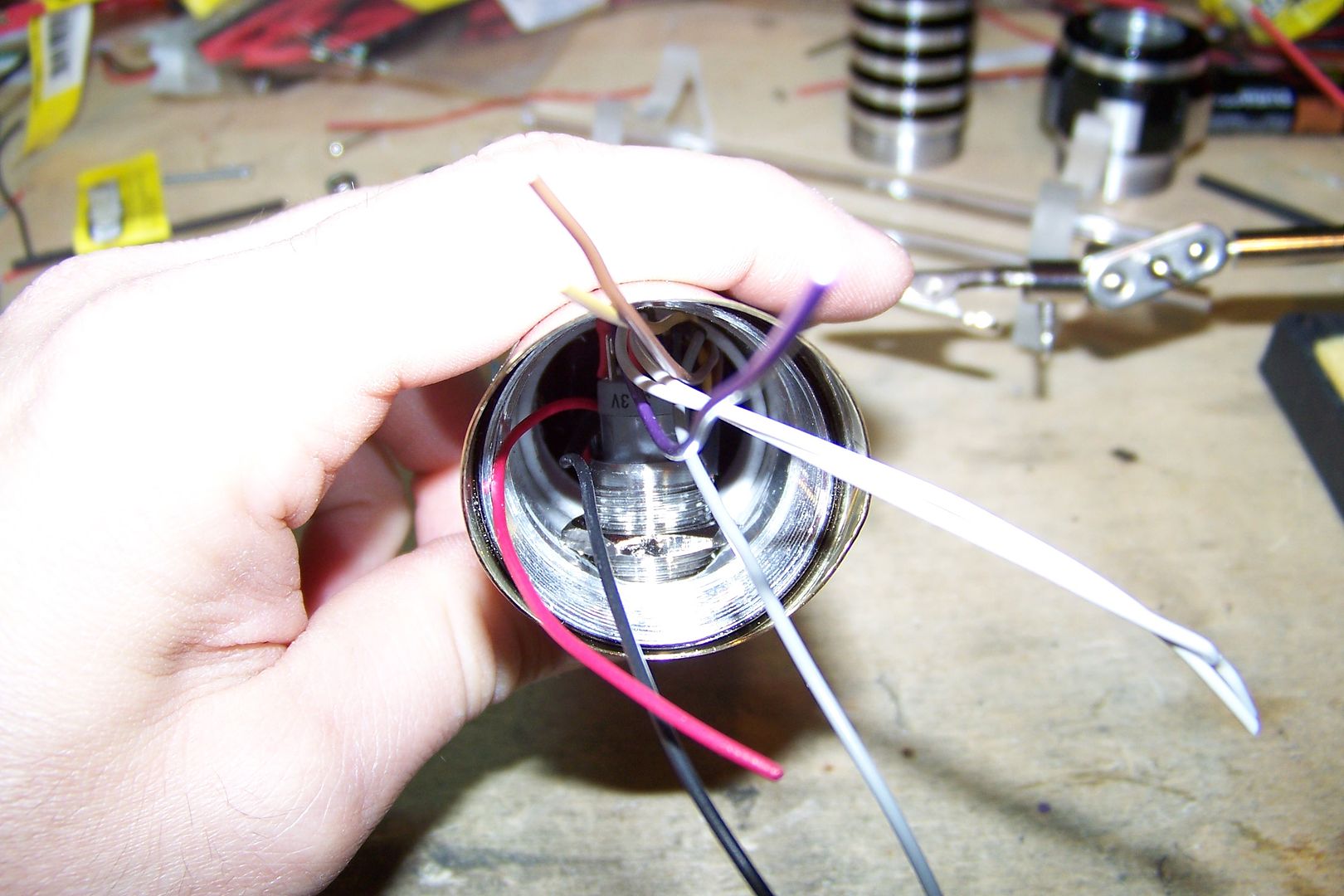
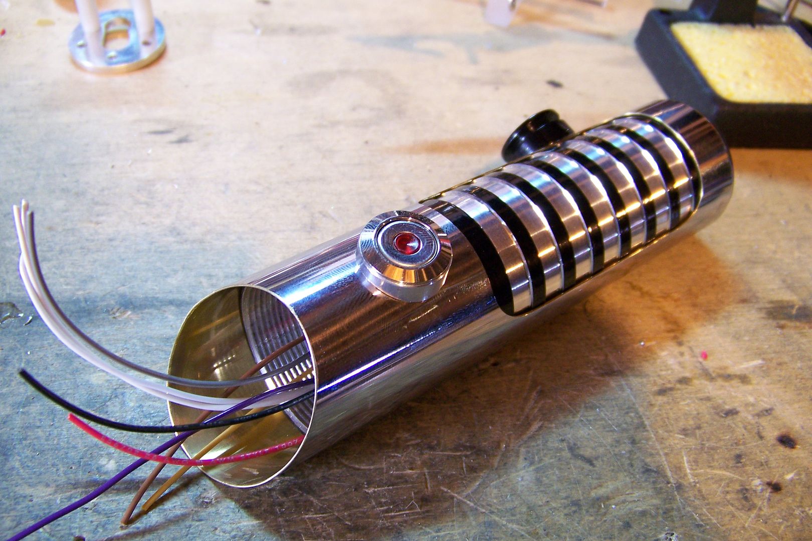
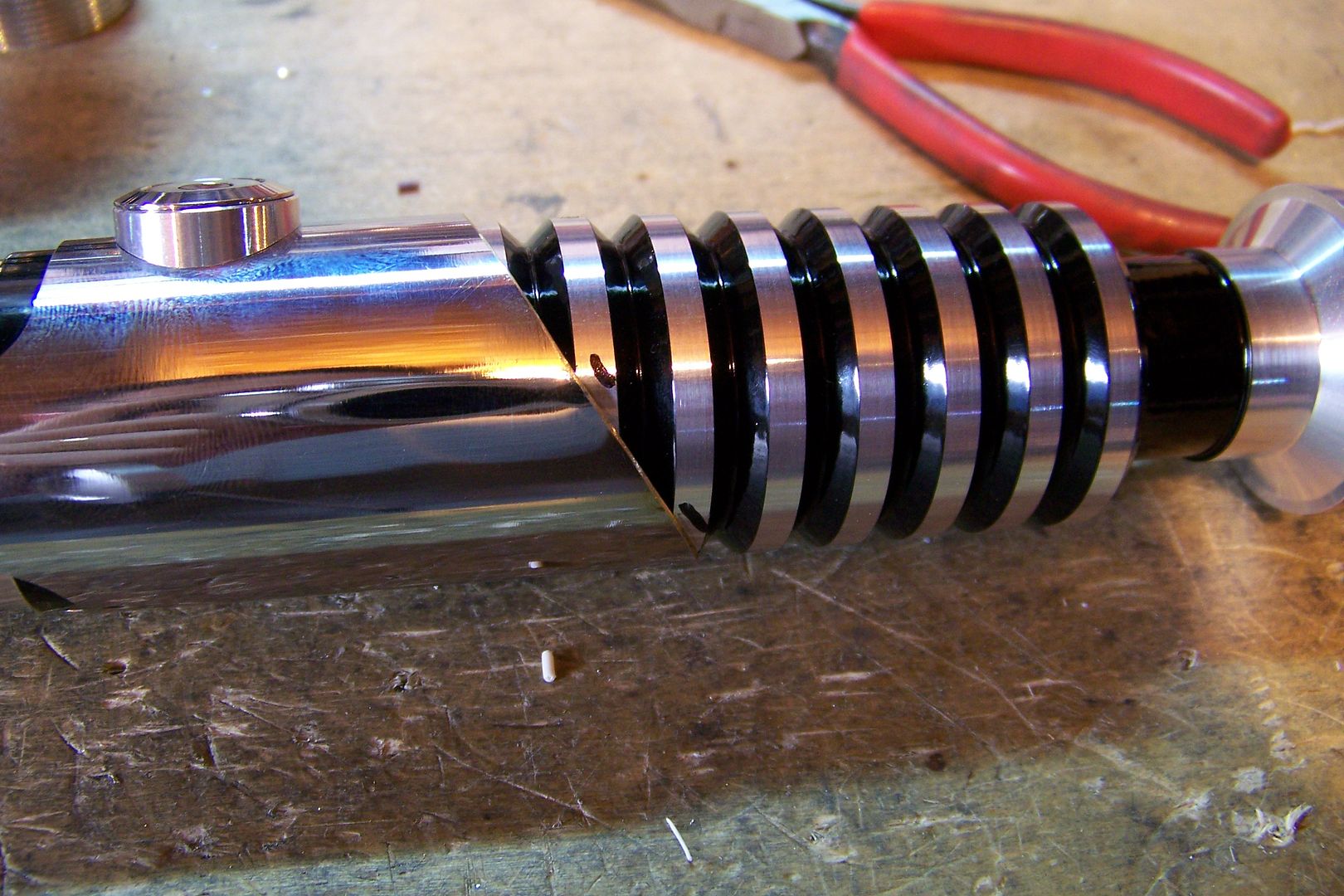
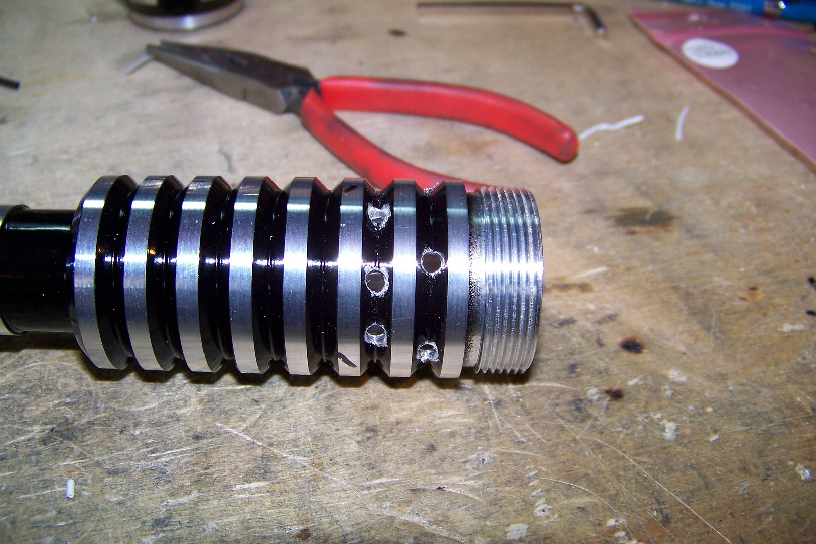
Here's the parts:
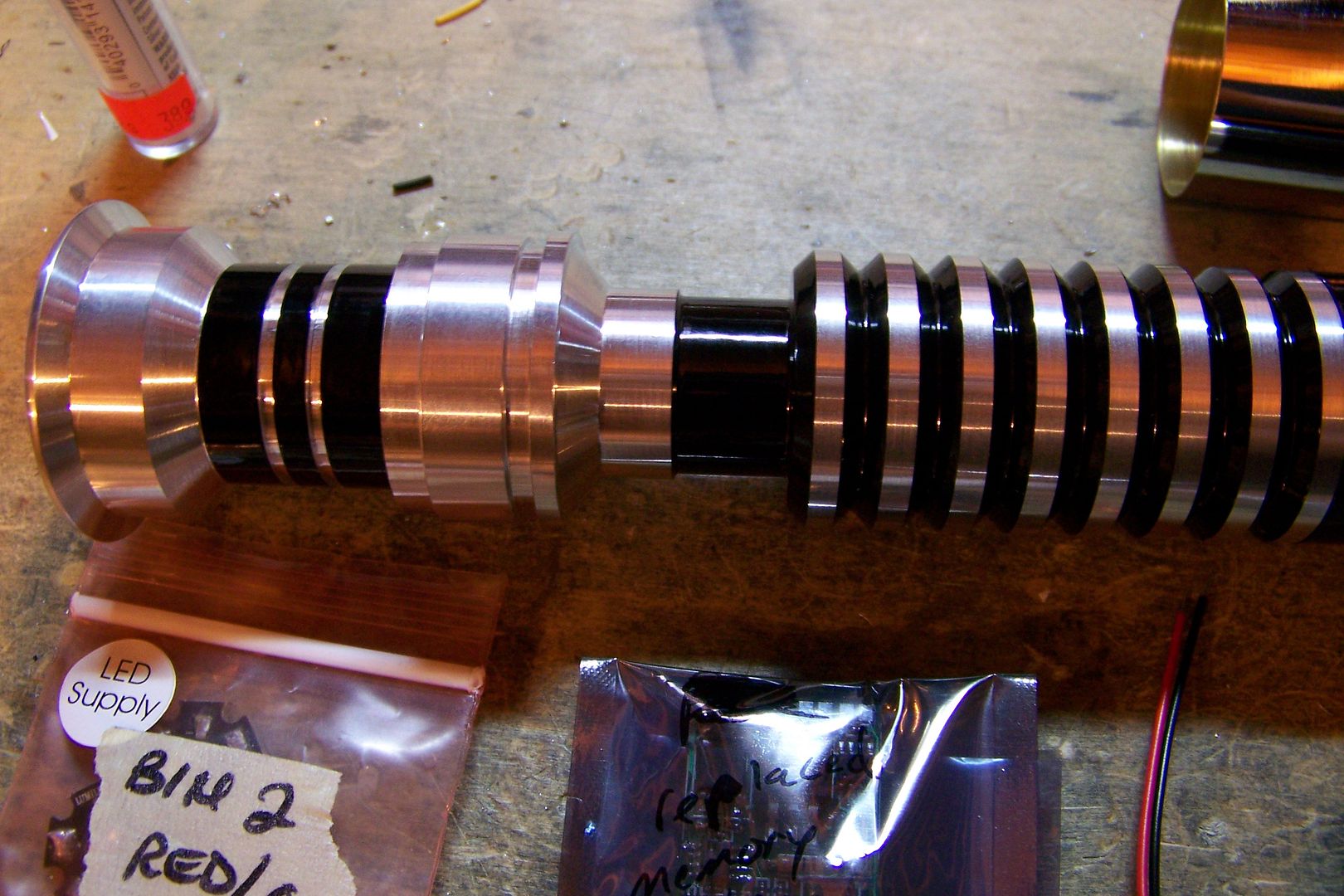
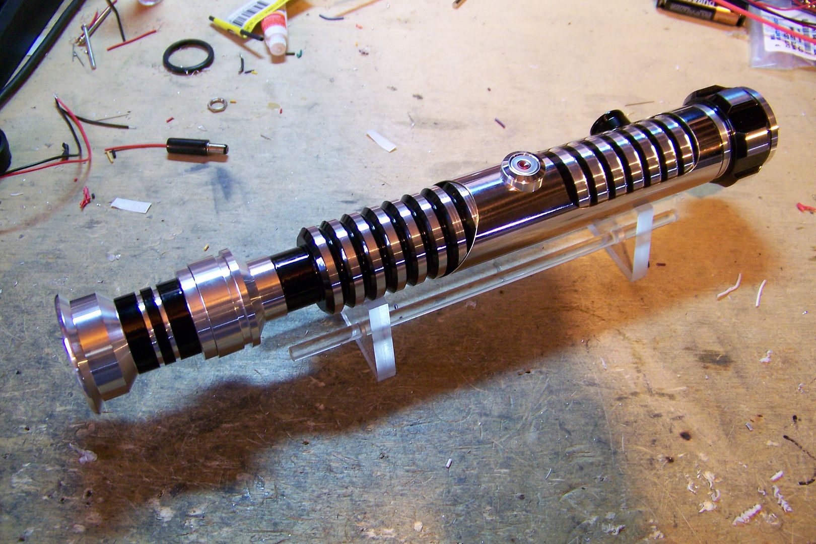
As usual, Tim did a fantastic job on all the custom work, from the grooves on the 5" ext. to the custom powder coat job on the blade holder, the ribbed/choke combo, and the pommel (which was the original from CS-24 that didn't look right with that saber when it was completed.)
This saber will simply use a couple of Trustfire protected Li-Ions to power it.
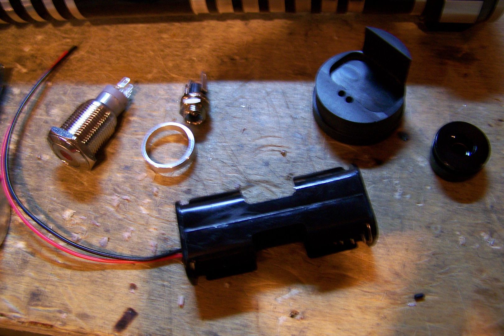
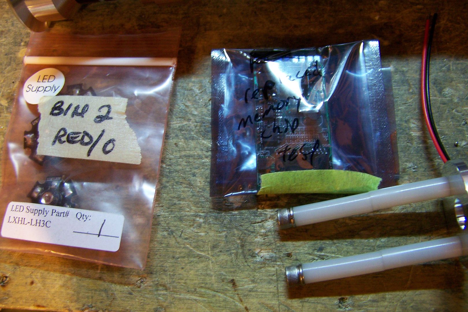
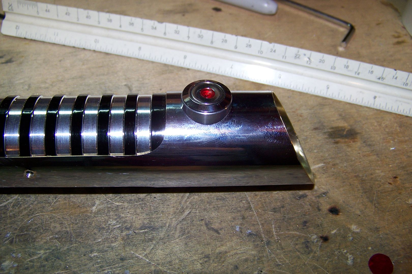
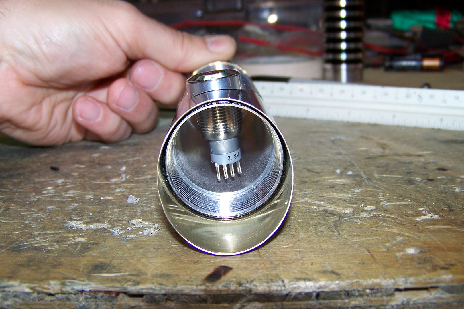
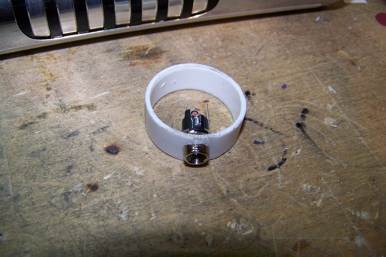
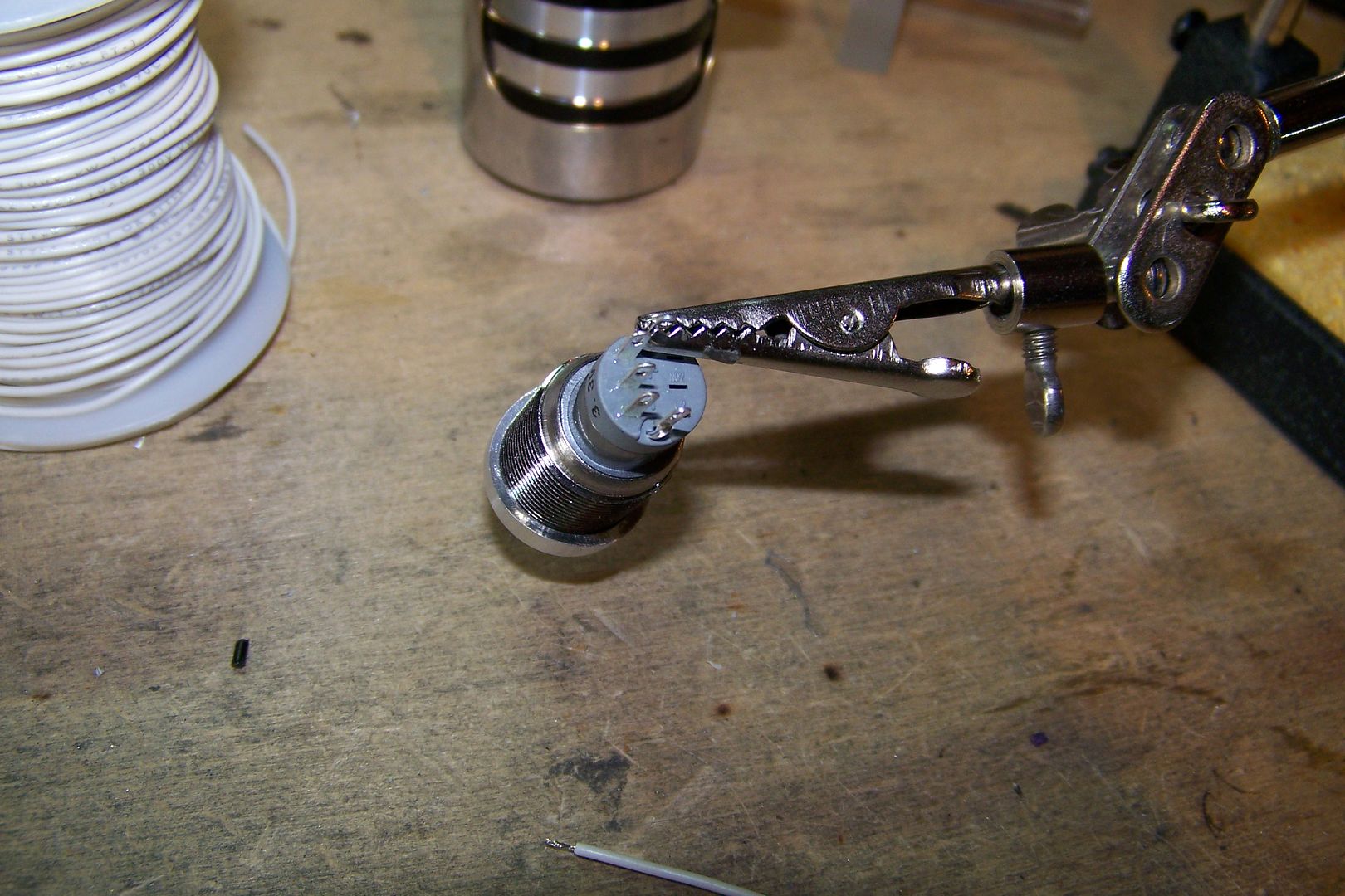
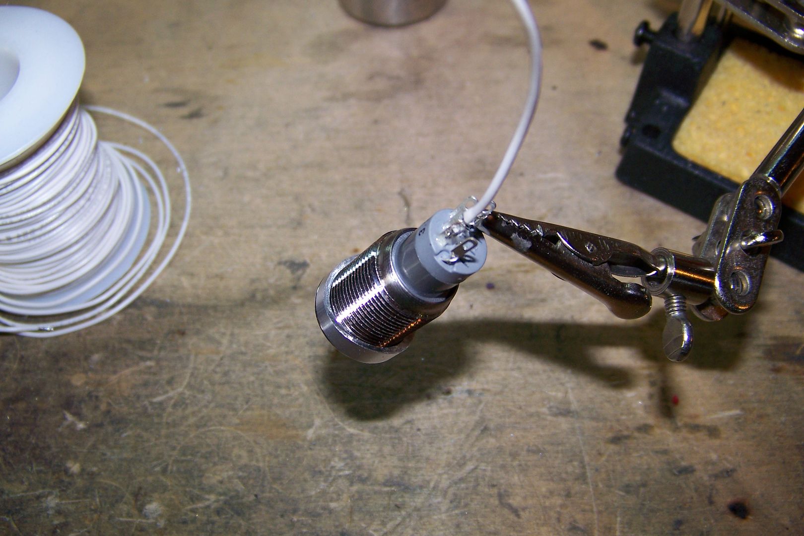
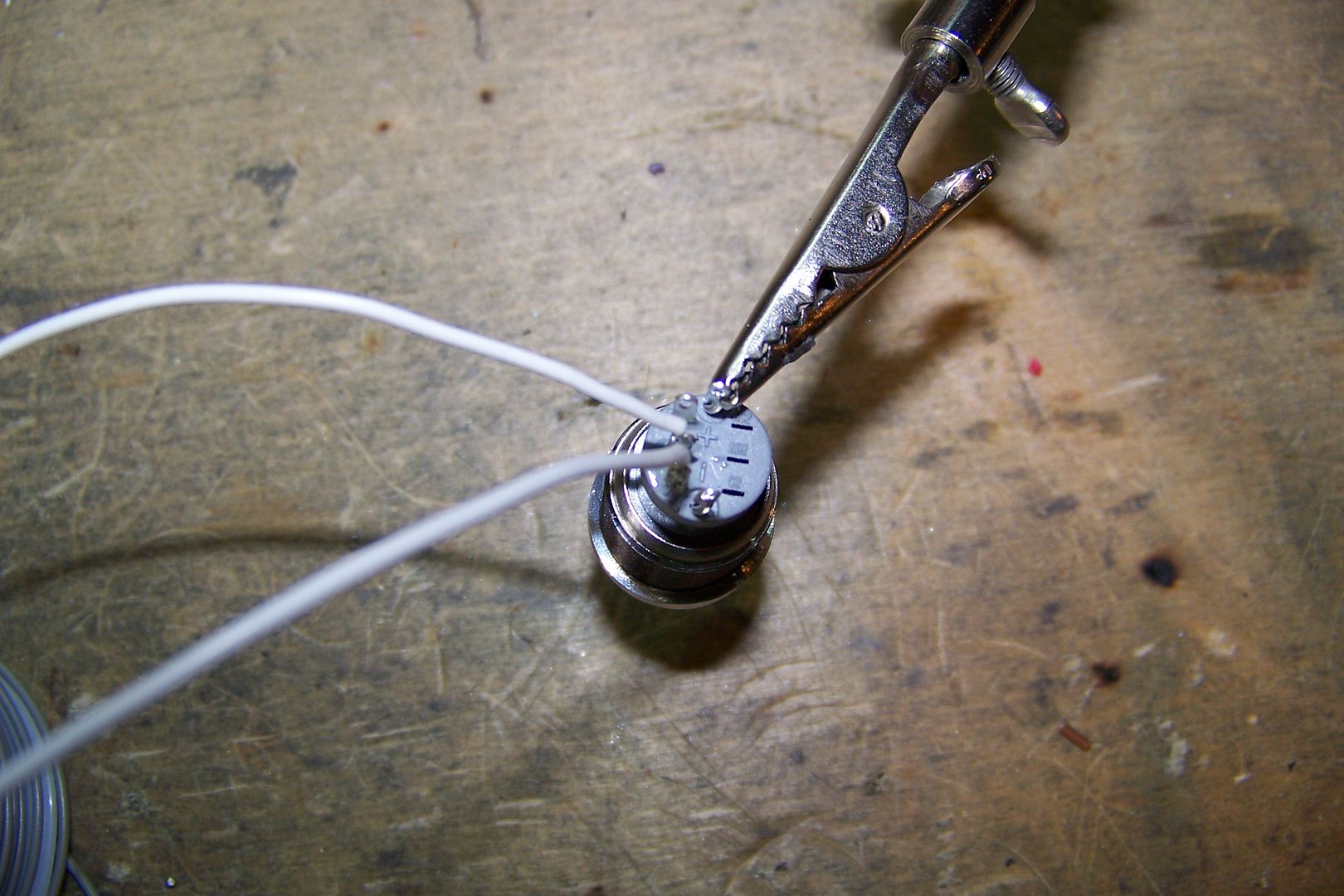
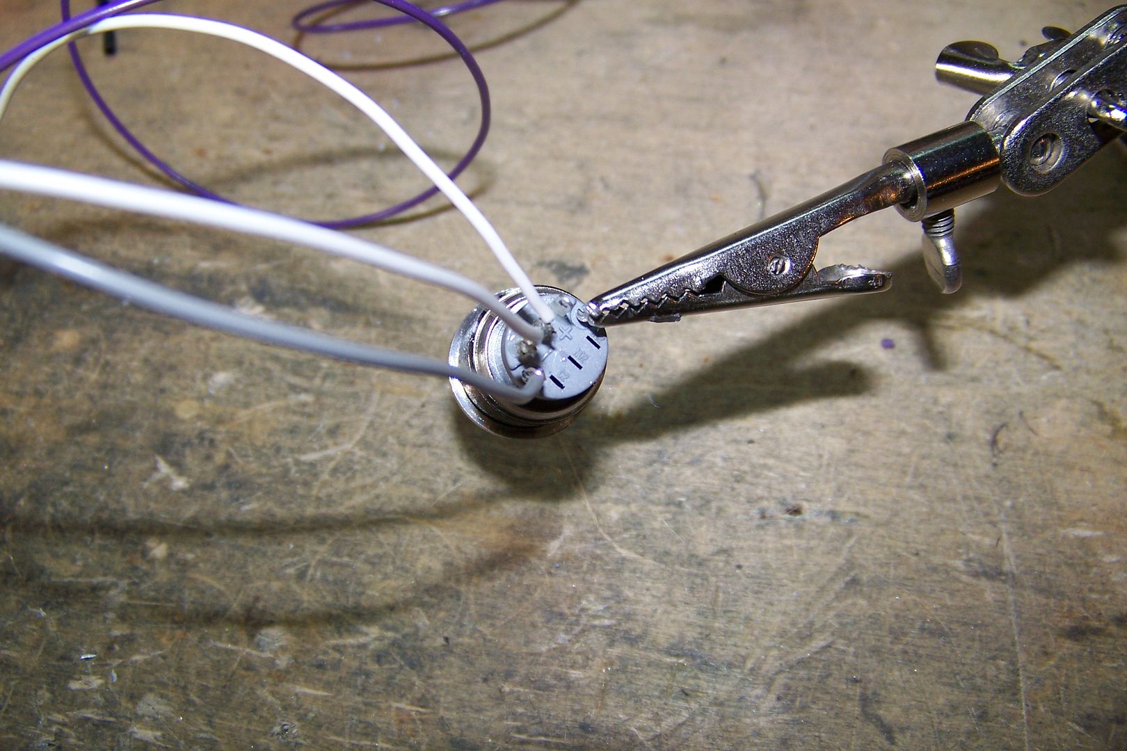
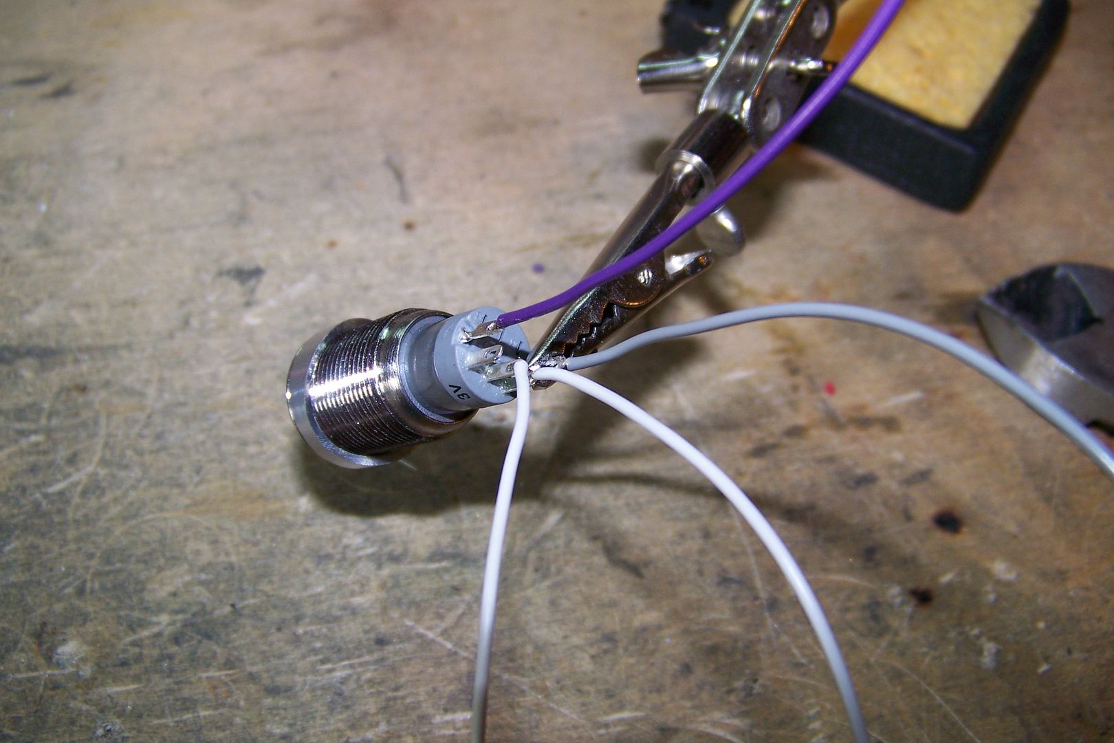
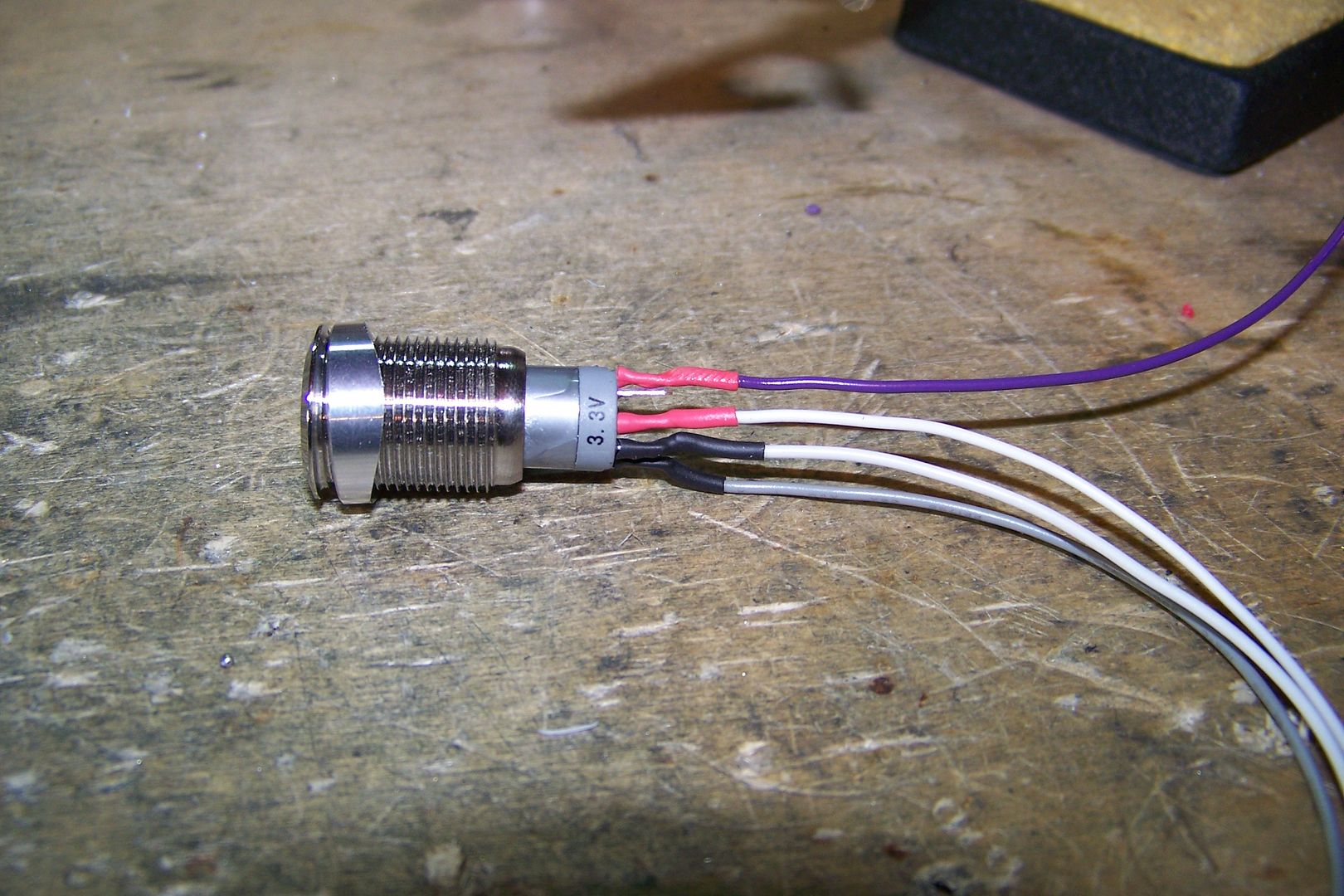
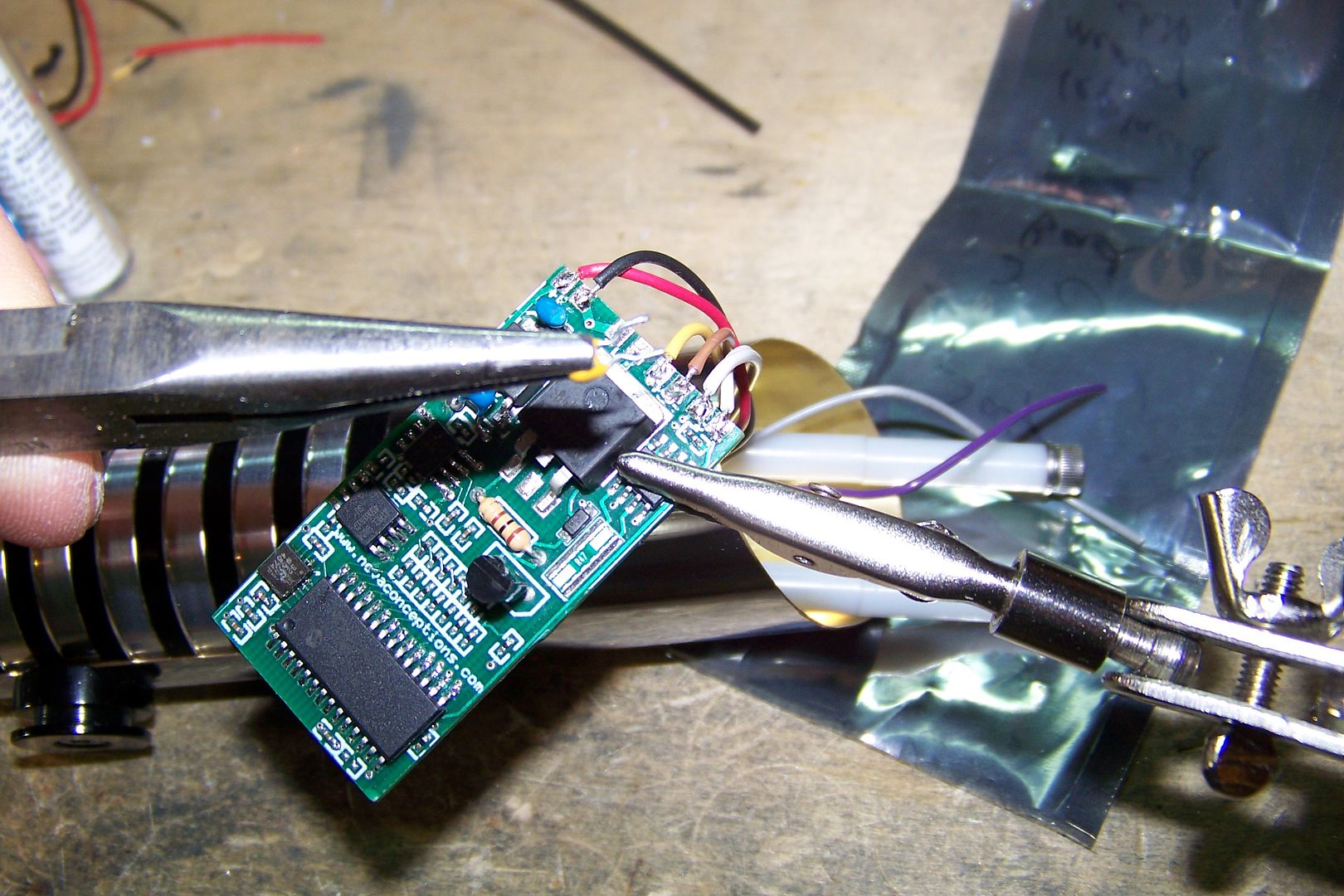
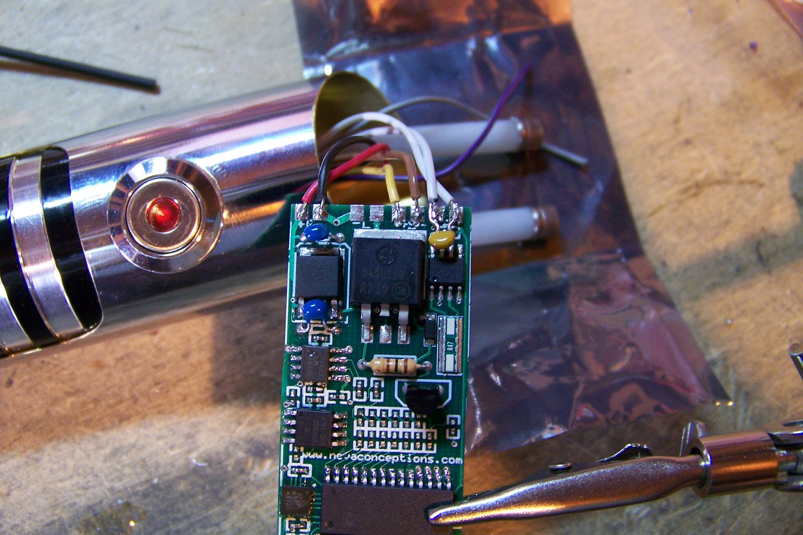
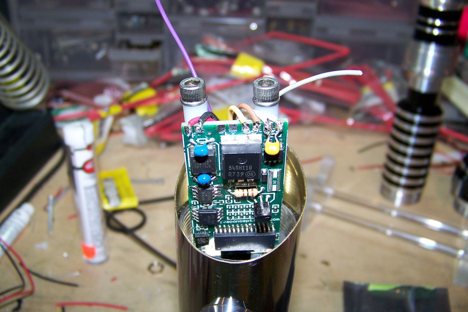
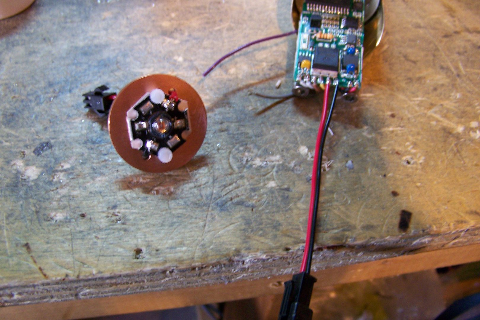
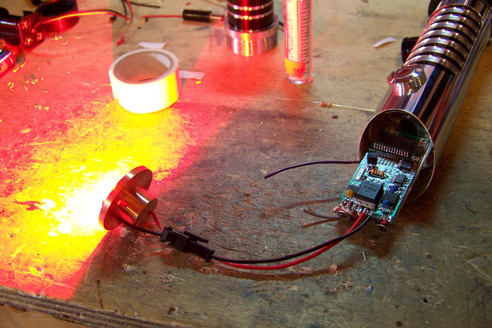
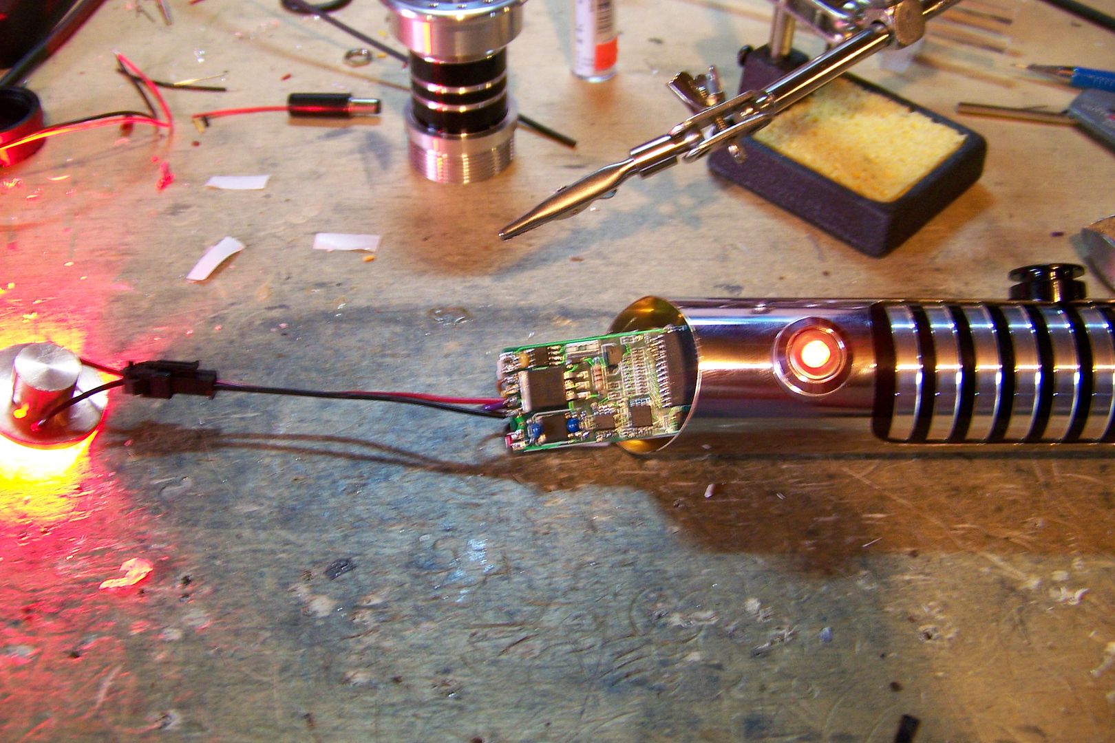
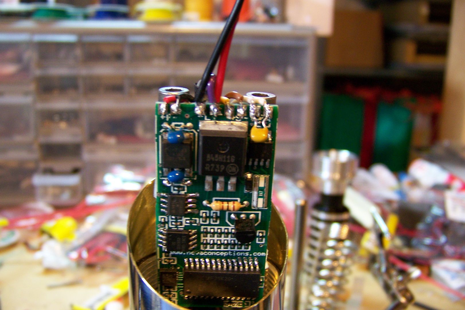
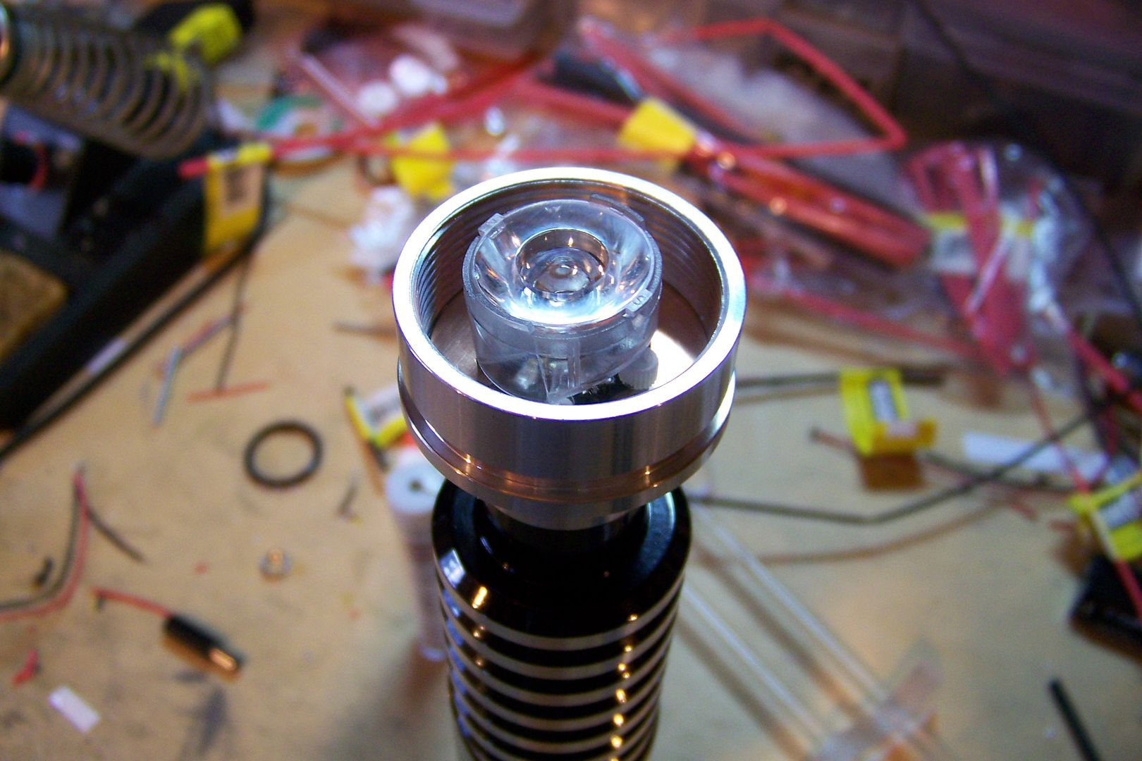
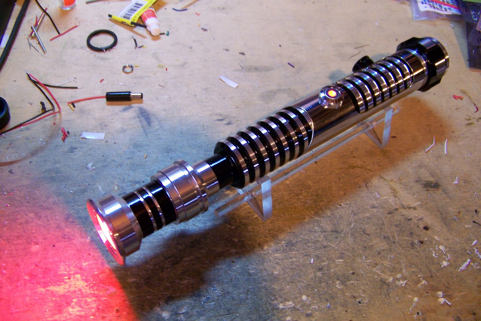
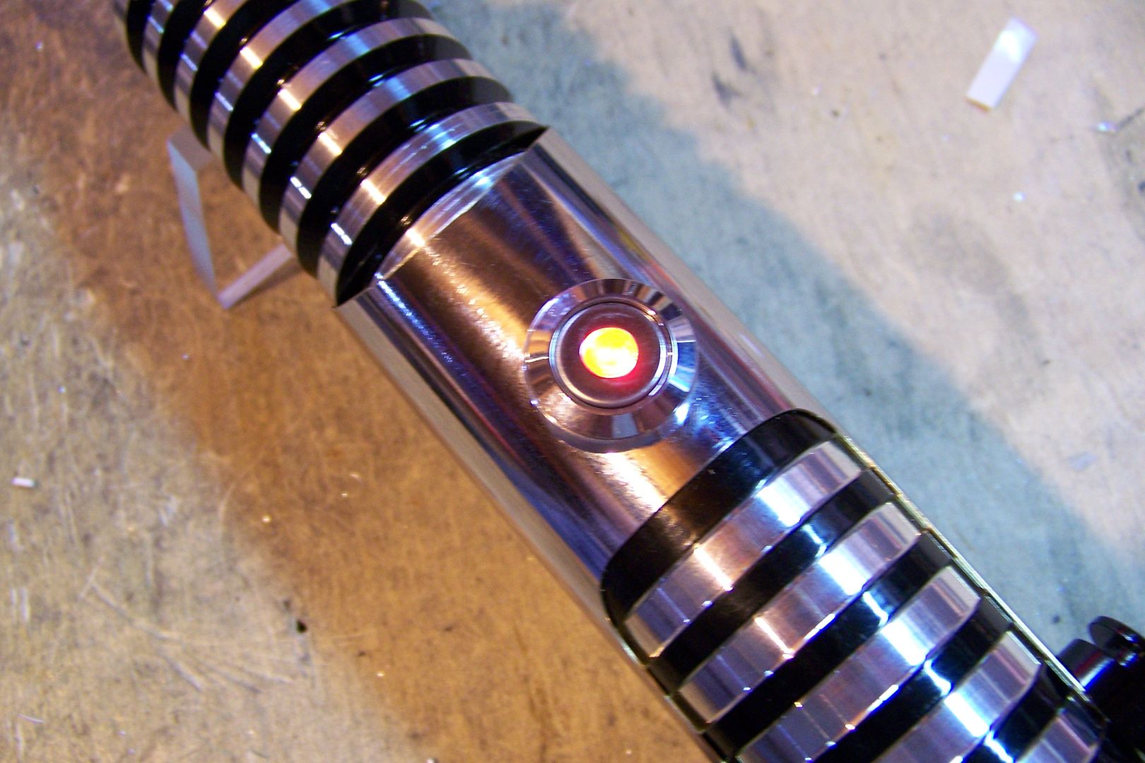
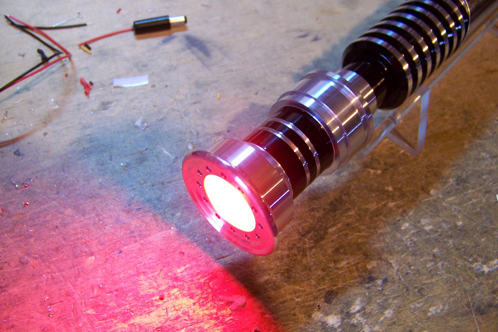
That's an Ultrasound 2.0....might be a 2.1 though, after having had Zook repair it with PIC and memory chip of another toasted board, though. The switch is red, and the blade led will be a Luxeon III Red/O.
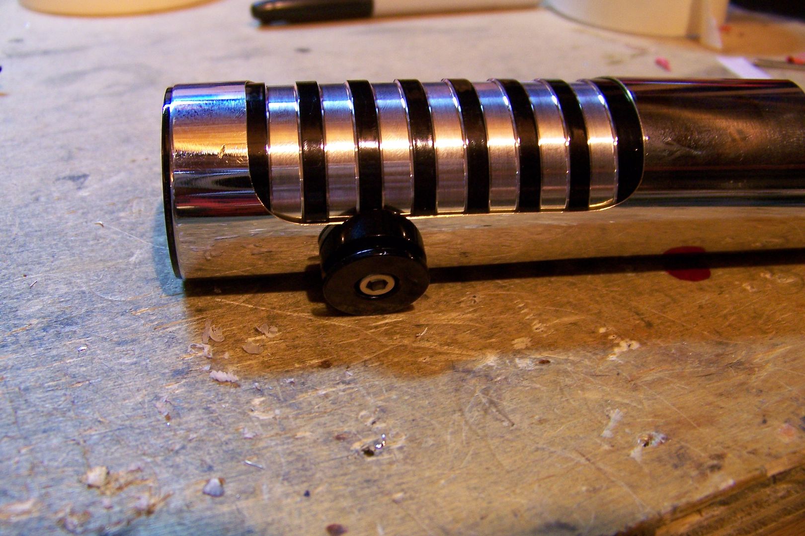
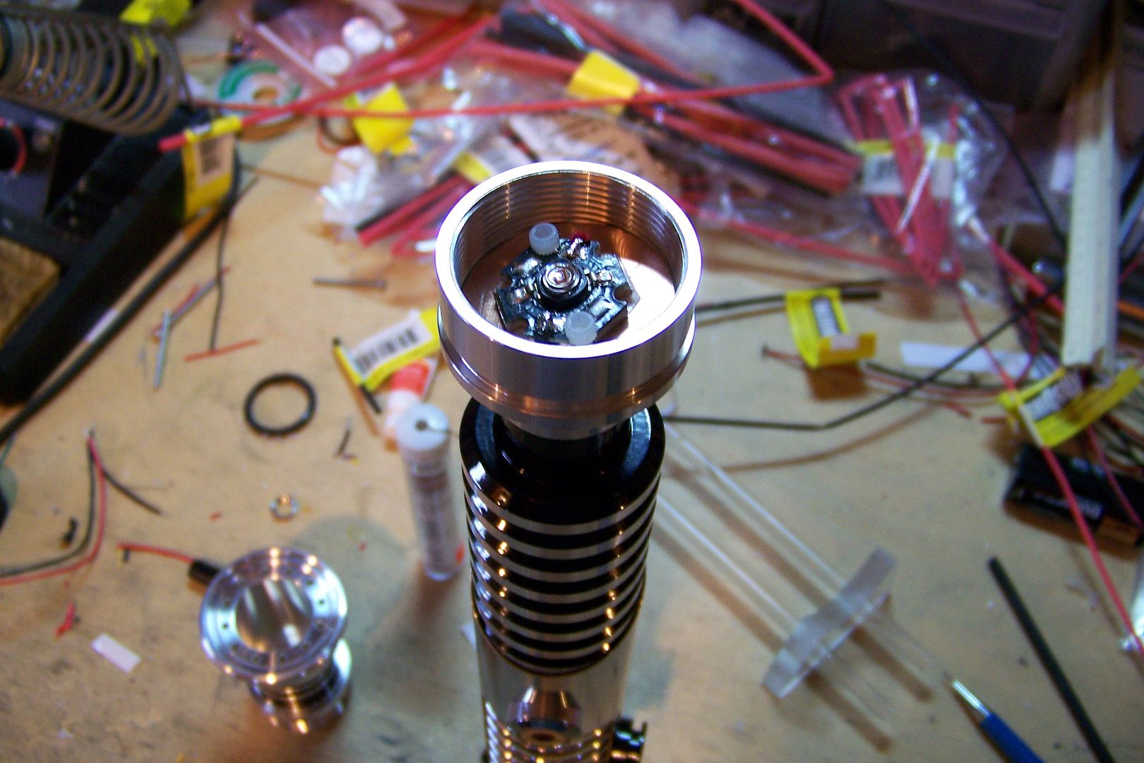
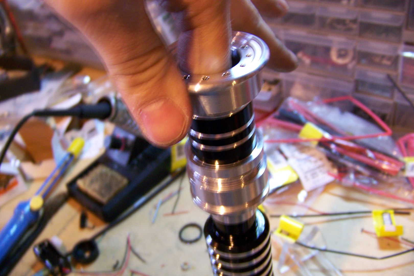
Now that I have the parts here, I'm not too sure I like the blade holder with the choke....looks kind of...off....to me. I may get another one to swap out with that one. Maybe a style 12, or 17. If I use either one, they'll be powder coated to match the saber, and I'll add a chrome shroud to it.
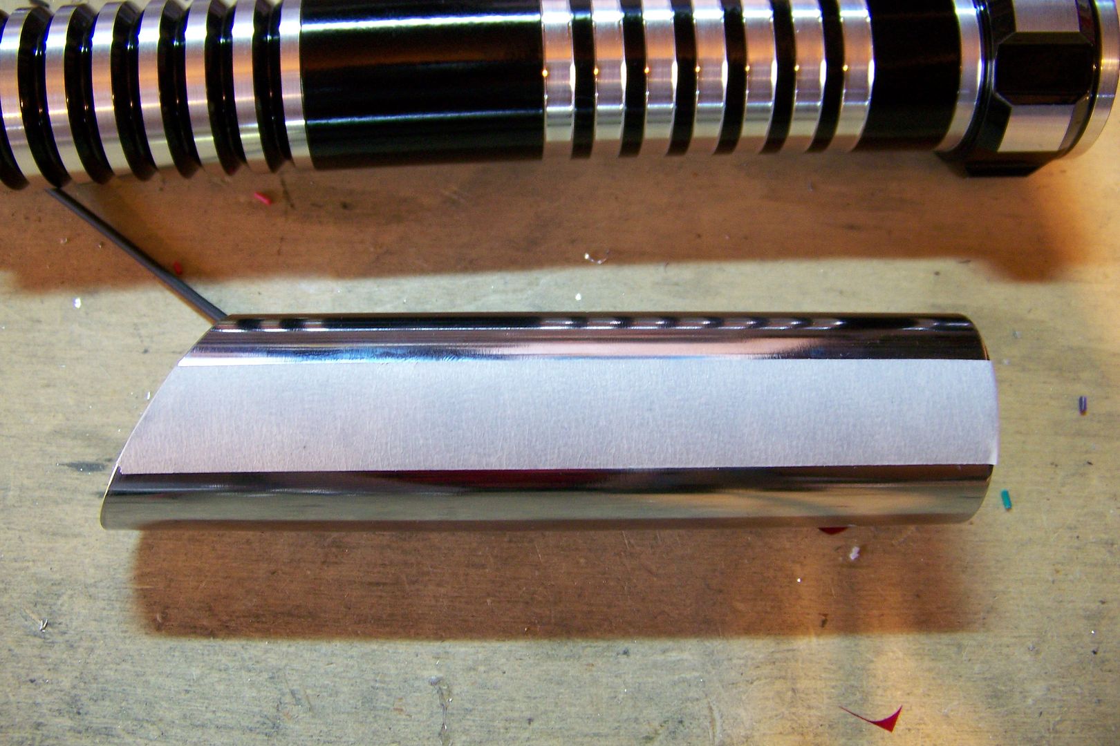
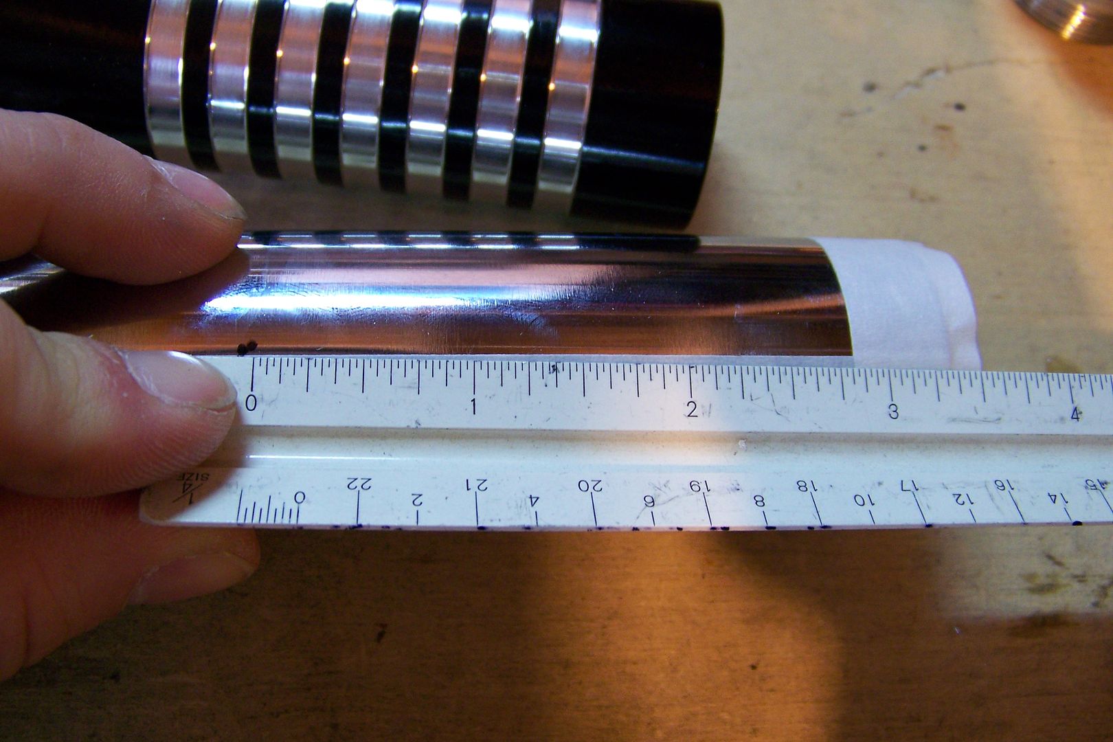
I'm also still working out the design for the sleeve. I'm thinking I'll do a double window on the rear grips, but I'm not sure what I'll do just yet on the other end of. Meditate on this, I will.


 Reply With Quote


Bookmarks