Results 1 to 7 of 7

Thread: how to wire a BuckPuck with a latching illiminated switch?

  1. #1

    Question how to wire a BuckPuck with a latching illiminated switch?

    Hi,

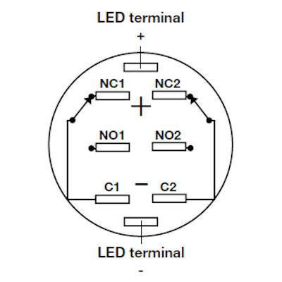
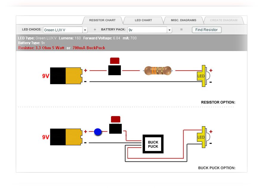
    I have done some searching on the forum already, but I haven't found the answer I need. I have a BuckPuck, and one of the latching illuminated switches. I am wondering what wire goes where? The diagram of the switch has several contacts on it. Also, the description states:
    There is no internal resistor on these so you need to use the correct resistor in order to not fry the LED. The LED has a forward voltage of 3.3V and runs at 20mA. 4.8V would use a 82ohm 1/4 watt resistor, 6V would use a 150ohm 1/4 watt resistor. If you are not sure which to use please ask.
    Do I need a resistor for the switch LED, or will the BuckPuck work with both? I am using a 9V battery. If I do need resistor, what type would I need?

    thanks!


  2. #2
    Council Member
    Jedi Council Member
    Jedi-Loreen's Avatar
    Join Date
    Dec 2005
    Location
    Not of this Earth
    Posts
    6,077

    Default

    Why are you using a 9V battery? For space constraints? 9Vs suck for powering our LEDs, they have terrible run times compared to multiple battery packs.

    You need a separate resistor for the LED in the switch, that's why the description in the Store is written that way.

    If you didn't, there's a Resistor Chart on the Store front page. You might discover some other interesting things in that chart, as well.
    In order to see the Light,
    you must sometimes risk the Dark.
    TCSS MODERATOR


    BLUE 8 Ready to ROCK and ROLL!

  3. #3

    Default

    Yes, I mainly use the 9V because of space. I might try a larger battery pack. I missed the resistor chart, the first time, thanks.

    So I'm still left with the question on how to wire the BuckPuck along with the resistor and illuminated switch. After looking at several charts, I think I might have it. I added the blue dot to the chart below to represent the resistor for the switch LED. Do I only use the LED+/- contacts on the switch? What about the other contacts?


  4. #4
    Council Member
    Jedi Council Member
    Jedi-Loreen's Avatar
    Join Date
    Dec 2005
    Location
    Not of this Earth
    Posts
    6,077

    Default

    If you check the Resistor Chart for the Illuminated switch, you'll see a wiring diagram for that, too.
    In order to see the Light,
    you must sometimes risk the Dark.
    TCSS MODERATOR


    BLUE 8 Ready to ROCK and ROLL!

  5. #5

    Default

    I'm having a similar problem, difference is I have a soundboard installed. When I wire the av momentary switch, the main led and switch led are on, but it won't turn off or on and there is no sound. What am I doing wrong?

  6. #6

    Default

    Is this placement of the resistor correct? I have a similar set-up, and I'm pretty sure I have the correct parts (please correct me if I'm wrong!) but I don't know how to wire them properly and I can't see any confirmation of whether the blue dot in the diagram is correct or not? Could you please tell me if this is the correct set-up and if not then what is? I checked the resistor chart for the illuminated switch but I can't really tell how that relates to the actual physical wiring set-up, plus it shows the resistor connected to red AND black wires so forming some sort of parallel circuit by the look of it?

    Also, on the switch there is a pair of brass (or brass-coloured!) loops and a pair of silver(ish) prongs - I'm guessing the relevant wires connect to the loops but being a complete novice I wanted to check rather than risking it! The items I'm using are as follows:

    16mm anti vandal latching amber ring switch
    buck puck 700mA 4-wire
    4xAAA battery pack (so 6V)
    220 ohm 1/4watt resistor
    rebel star amber LED & heatsink module (the pre-wired easy option!)

  7. #7

    Default

    I haven't worked with one of these switches yet, but it looks like the brass loops are for the power(+/-, the order shouldn't matter) and the prongs are for the LED. The led will need the resister (as you know), and will connect to - of the battery pack or sound board.
    Here is a quick pic of how it could be done.
    switch led wiring.jpg
    Note: I don't actually know which prong is + or -, the pic is just an example

    It will all depend on your wiring setup, but I think you got the gist of it.


    Happy Sabering
    ~ The Yin ~

    “Yeah I’m pack’n heat! It’s to prevent anyone from making me cold.”

    For the saber building Younglings and Padawans: Basic Saber Building and The Saber Building Dictionary!

Bookmarks

Posting Permissions

  • You may not post new threads
  • You may not post replies
  • You may not post attachments
  • You may not edit your posts
  •