Page 1 of 4 1 2 3 ... LastLast
Results 1 to 10 of 36

Thread: Jay-gon Jinn's Chrome Saber 25(Seoul P4, w/illuminated AV switch, non-sound stunt)

  1. #1

    Default Jay-gon Jinn's Chrome Saber 25(Seoul P4, w/illuminated AV switch, non-sound stunt)

    This will cover the complete build of Chrome Saber 25 (CS-25) from start to finish. I'll be using a simple non-sound resistored set-up for this saber, and will be cutting a chrome sink tube sleeve for it.

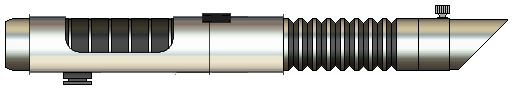
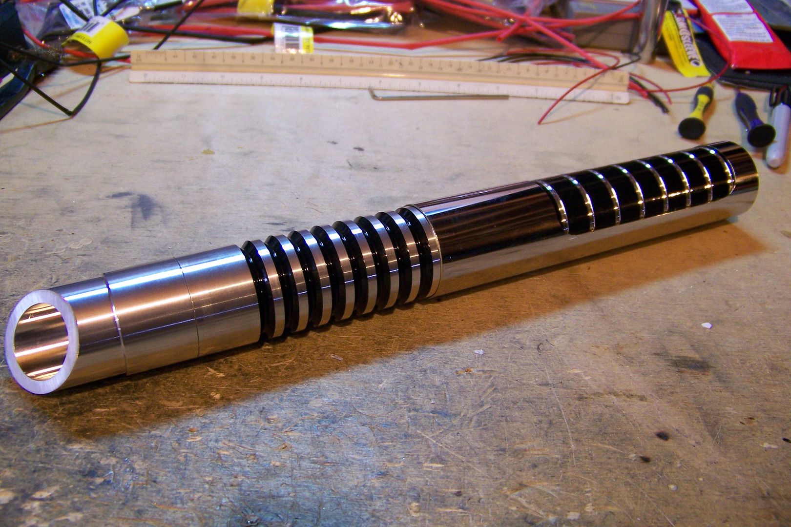
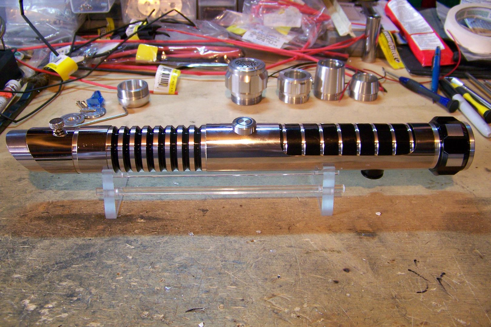
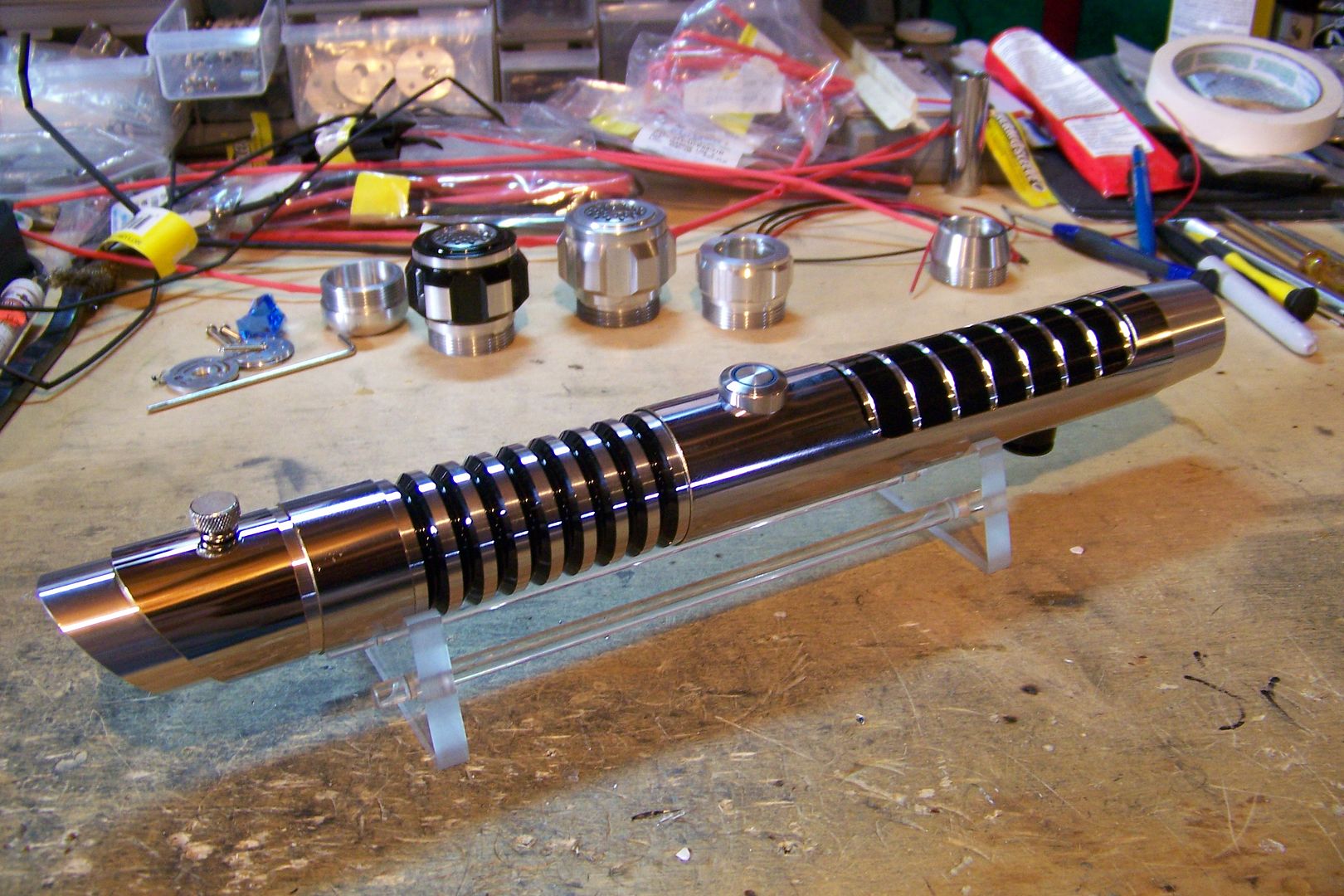
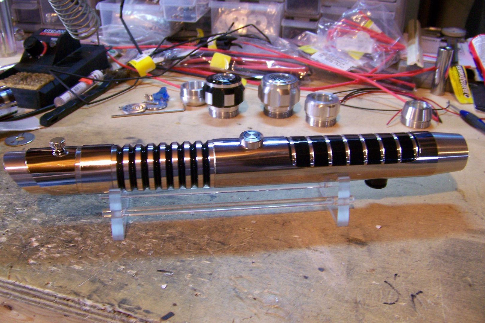
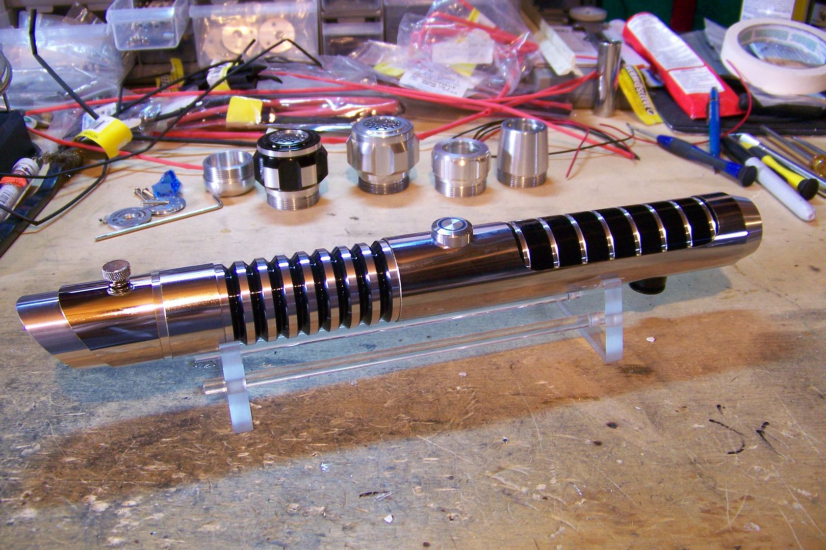
    Here's the basic render:
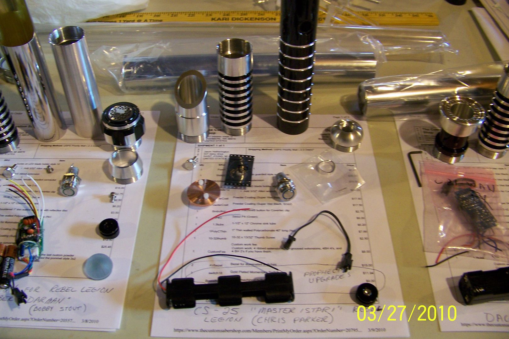
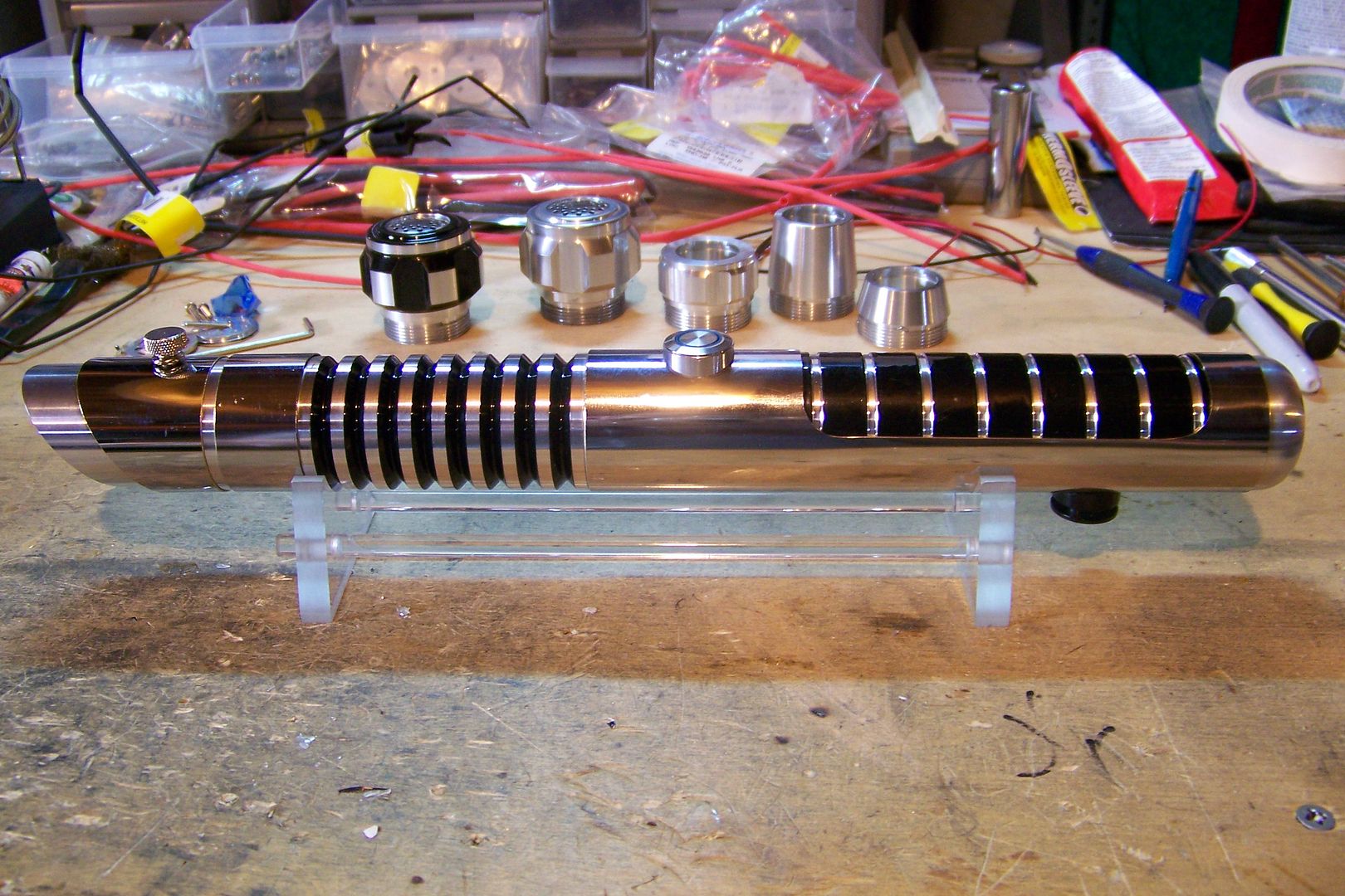
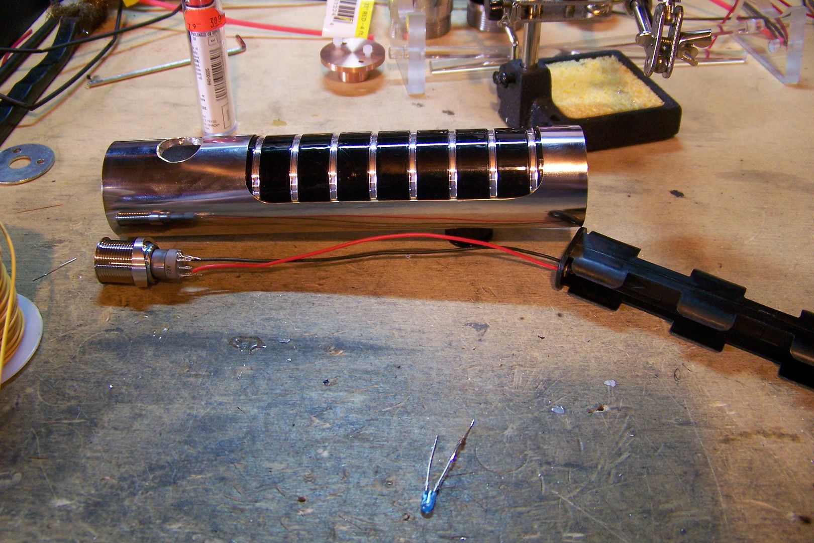

    The Parts:


    Parts list:
    • MHS blade holder style 12
      MHS ribbed extension; powder coated in RIB3 style
      MHS hilt style 2 w/guarded switch hole; powder coated in SH22 style
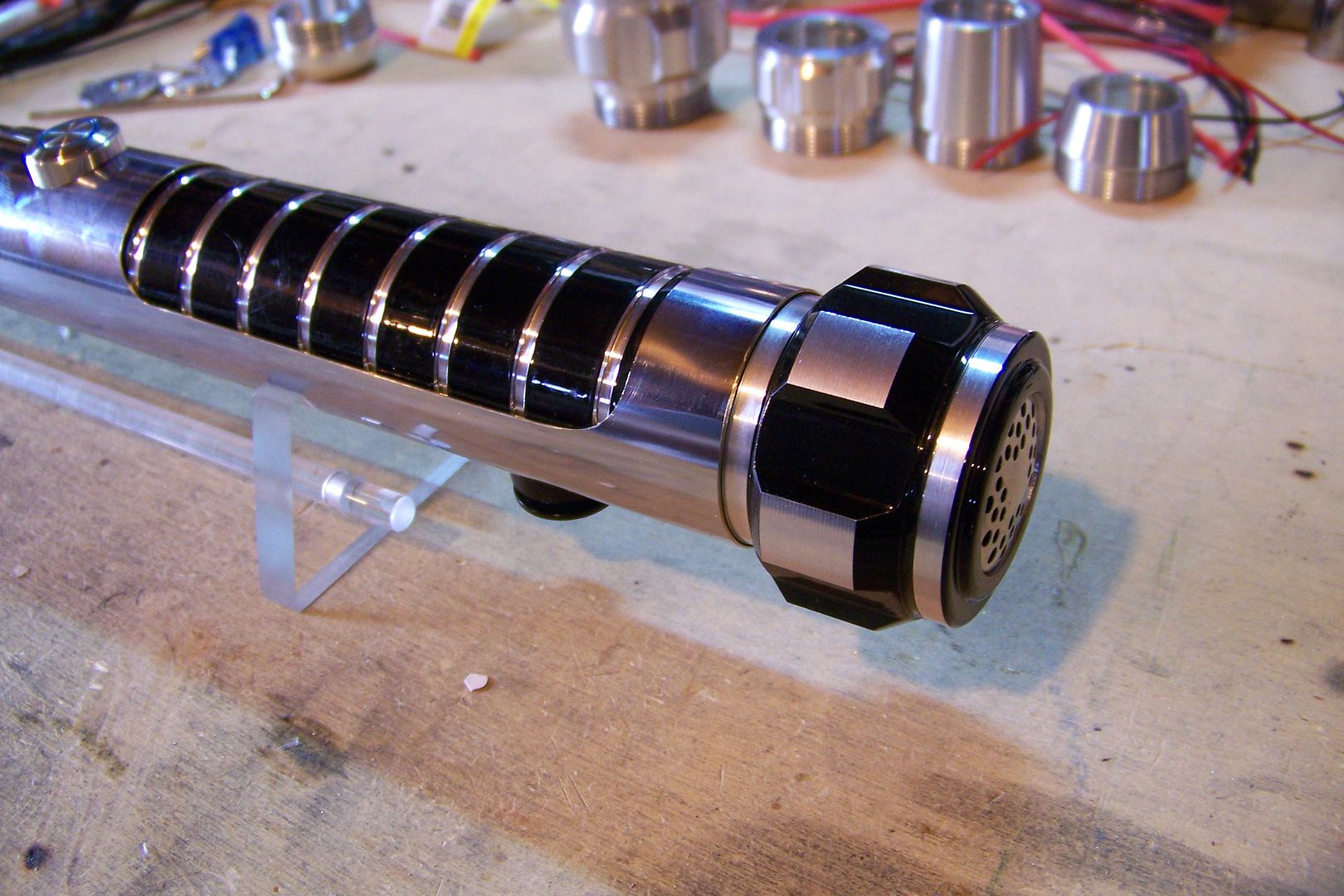
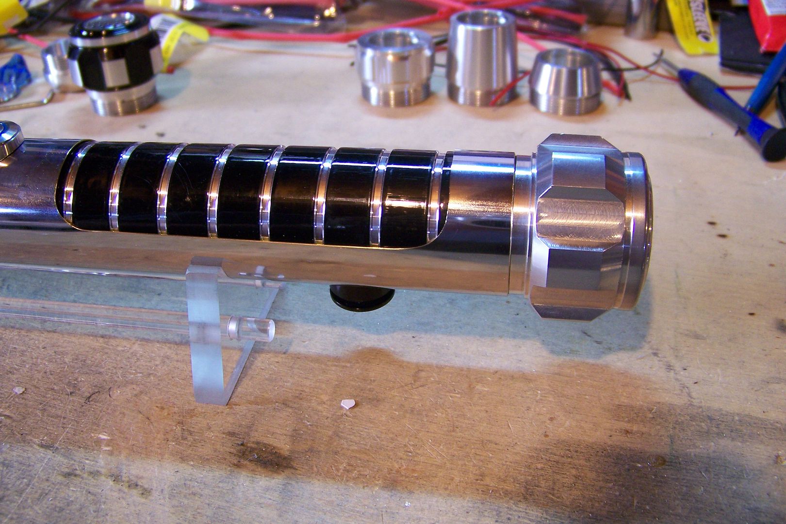
      MHS pommel style 1
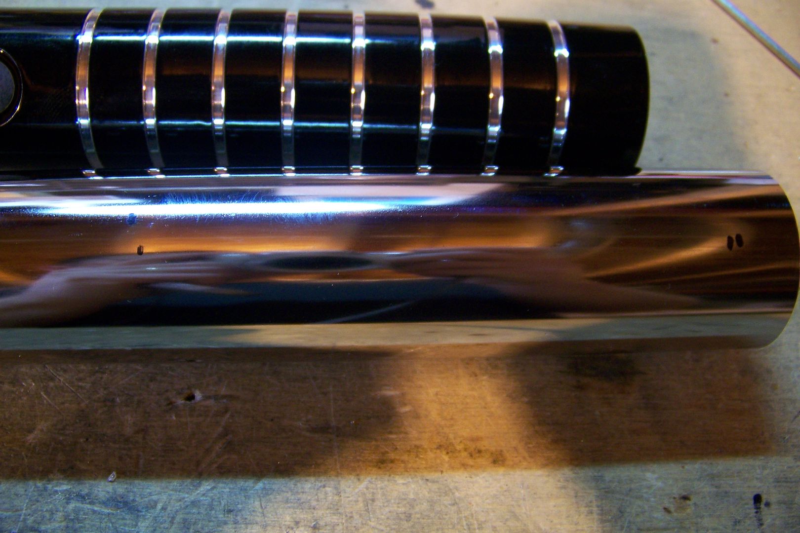
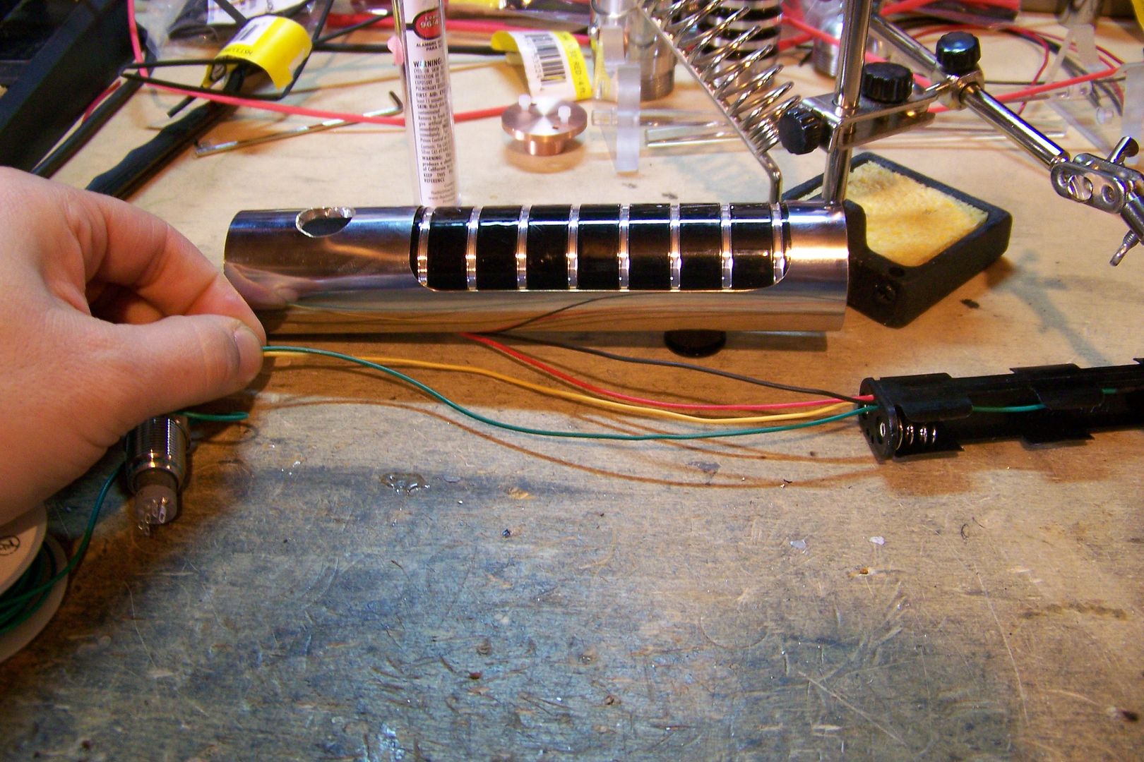
      7" chrome sinktube; 1 1/2" O.D.
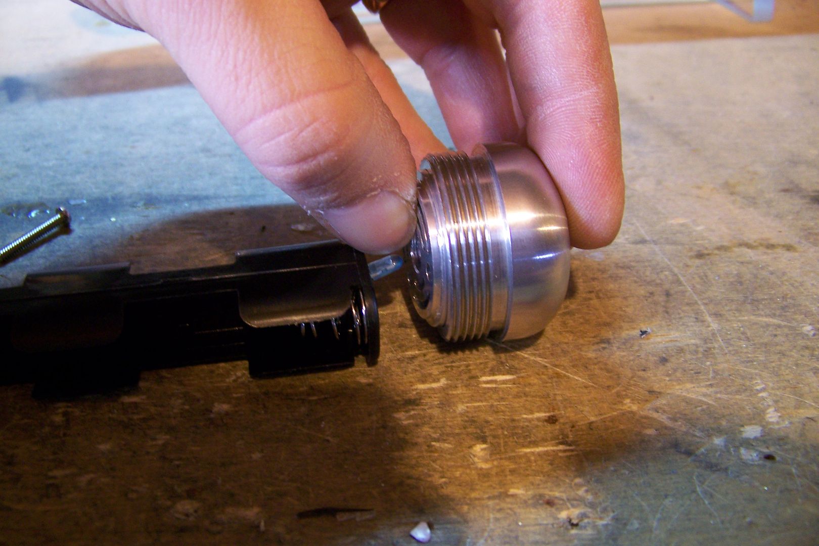
      Machined covertec button; black anodized
      8-32 x 1/4" socket head cap screw
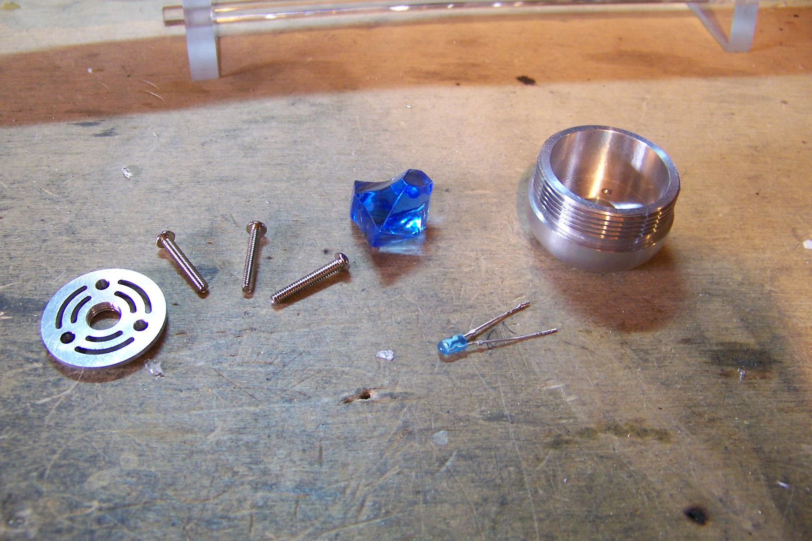
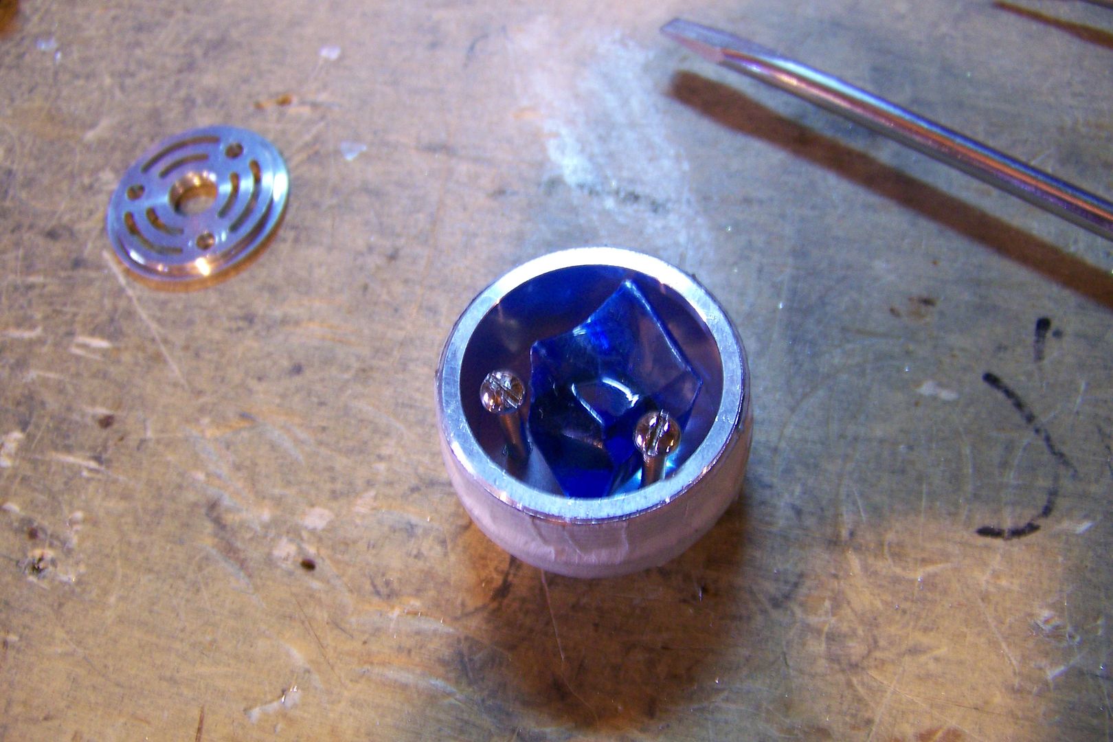
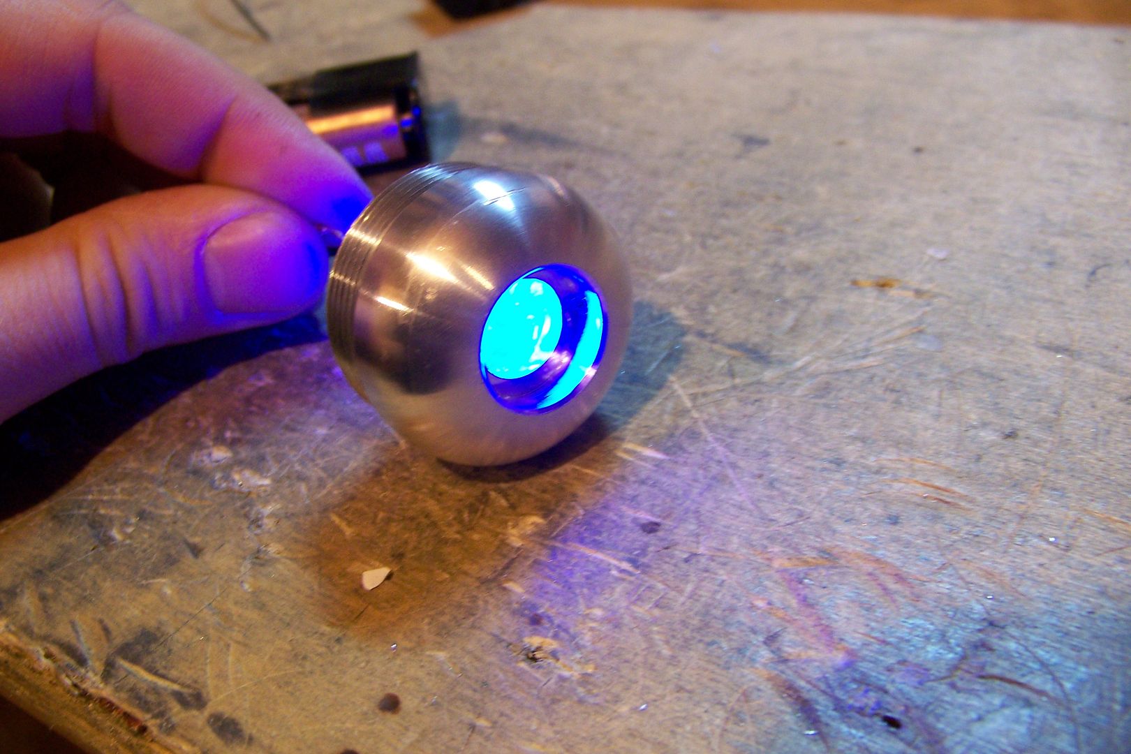
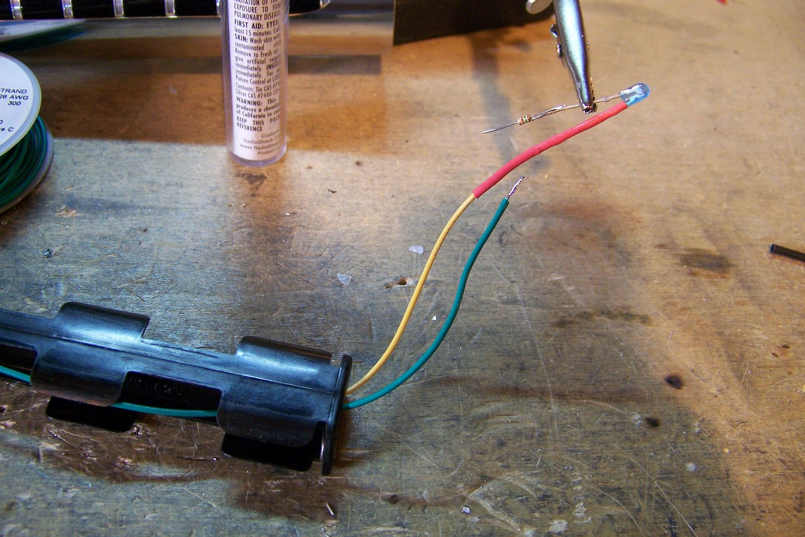
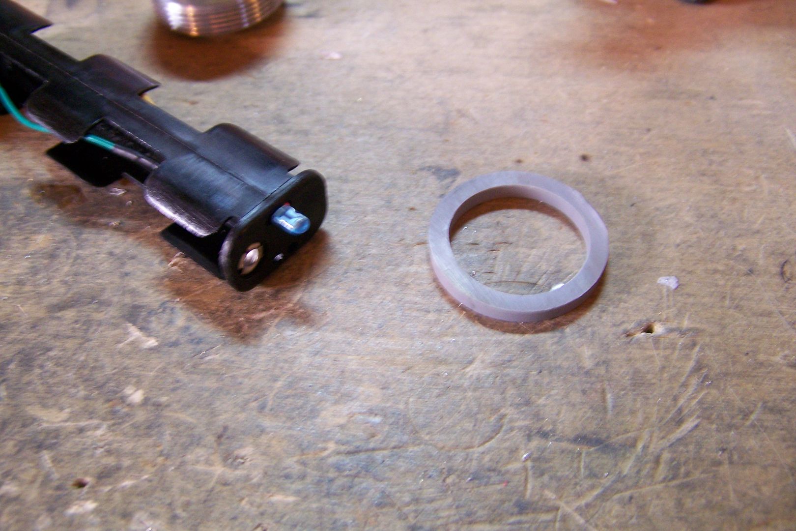
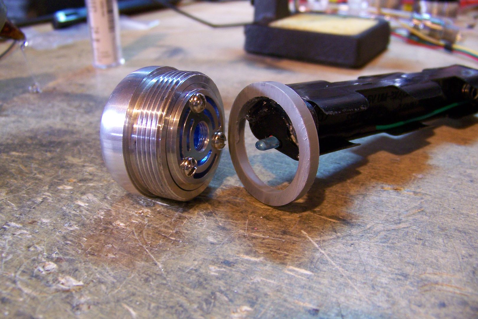
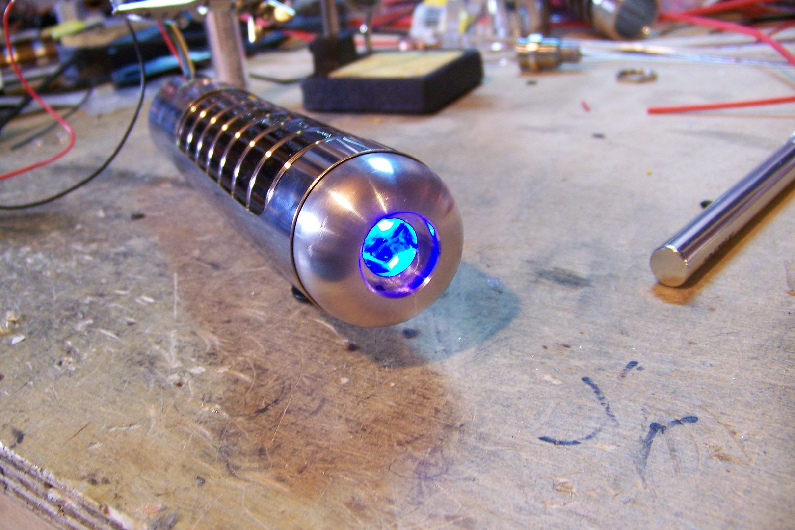
      illuminated anti-vandal switch w/blue ring; 12v led (not from TCSS)
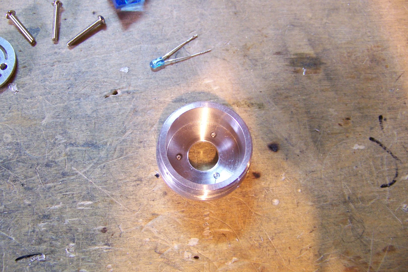
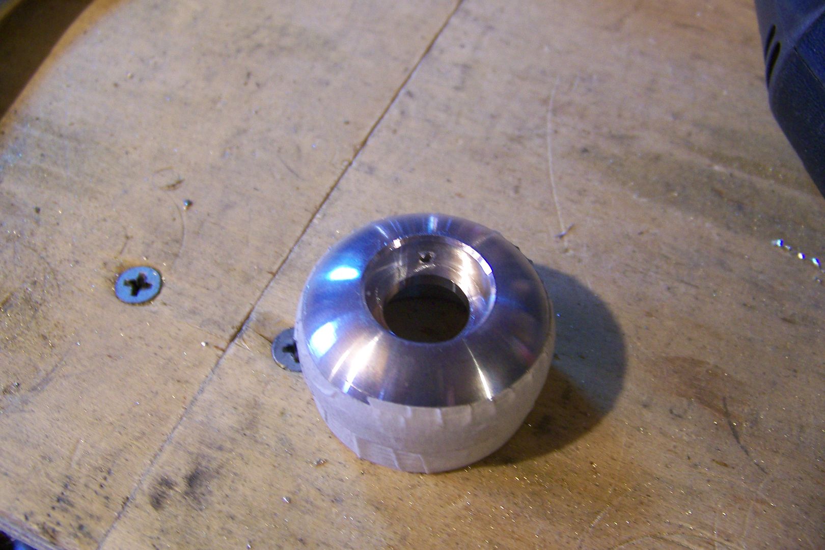
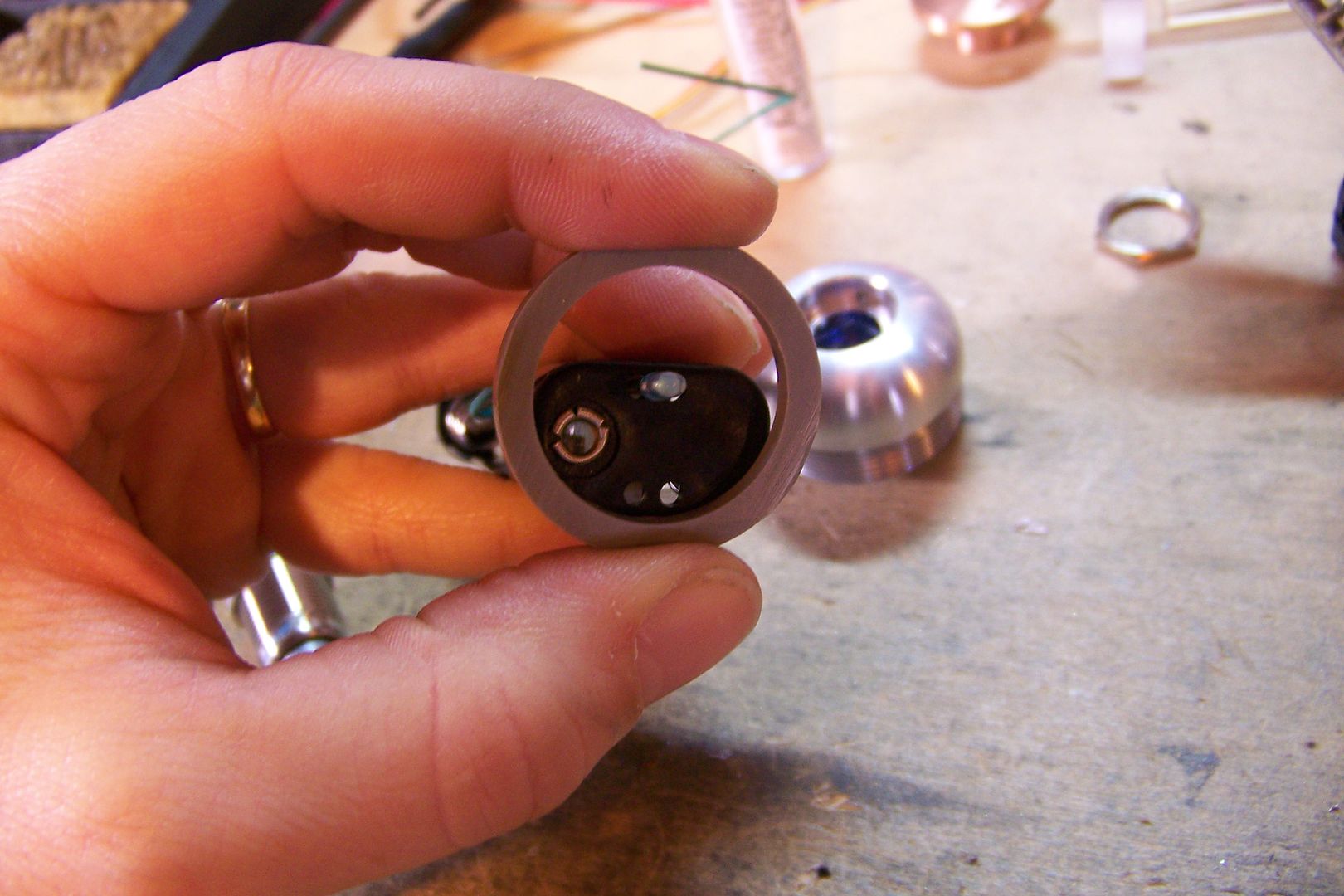
      Machined bezel for anti-vandal switch
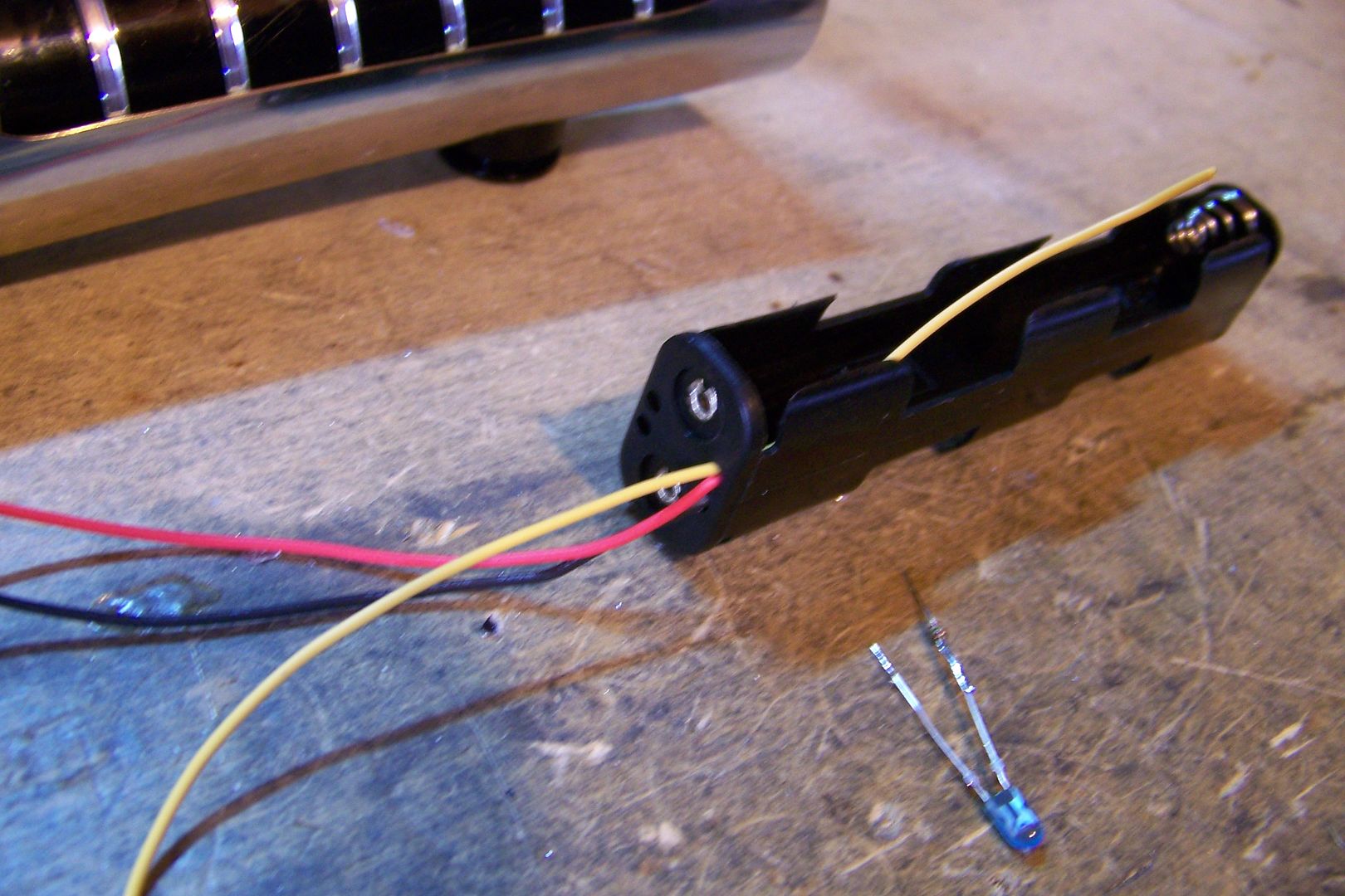
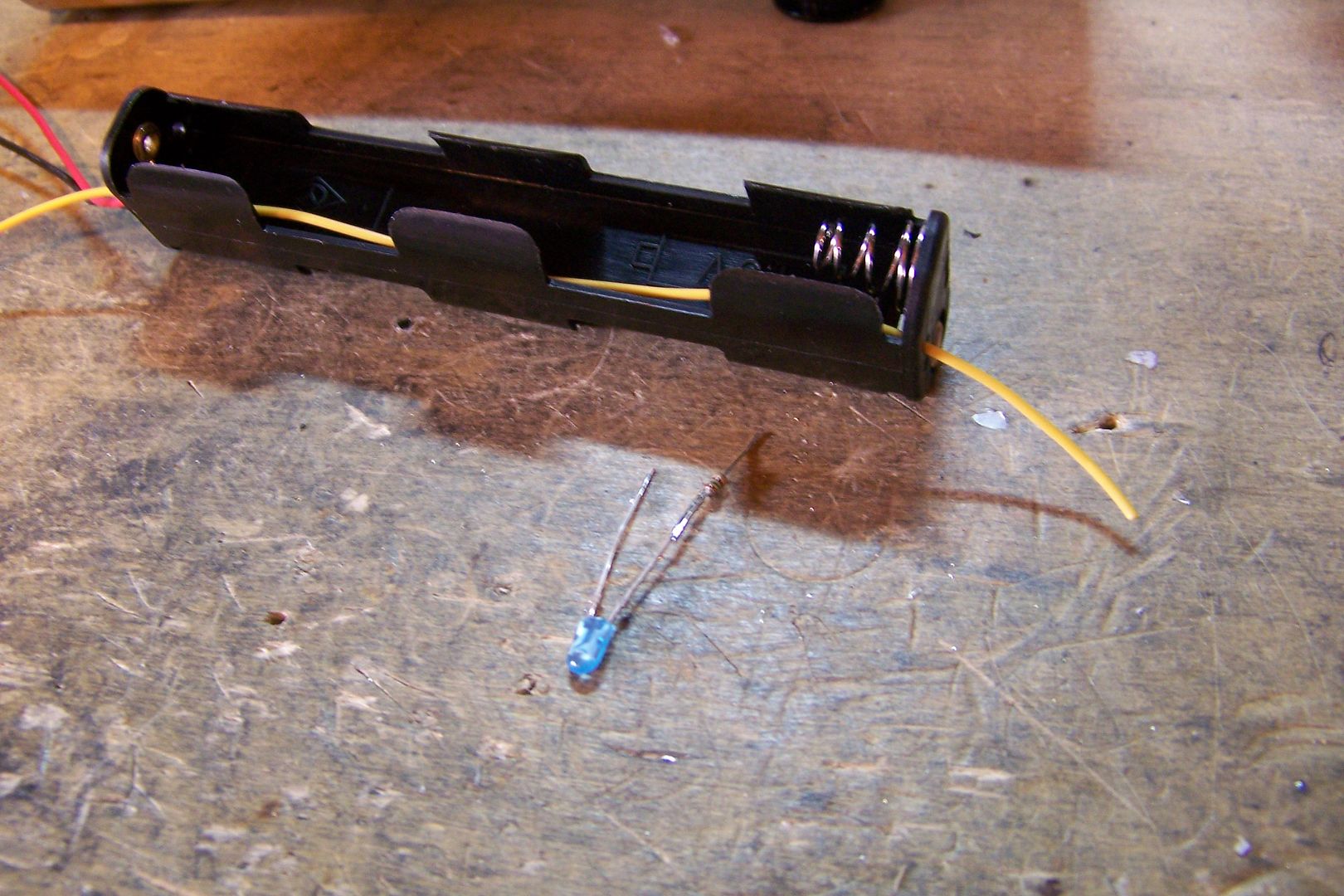
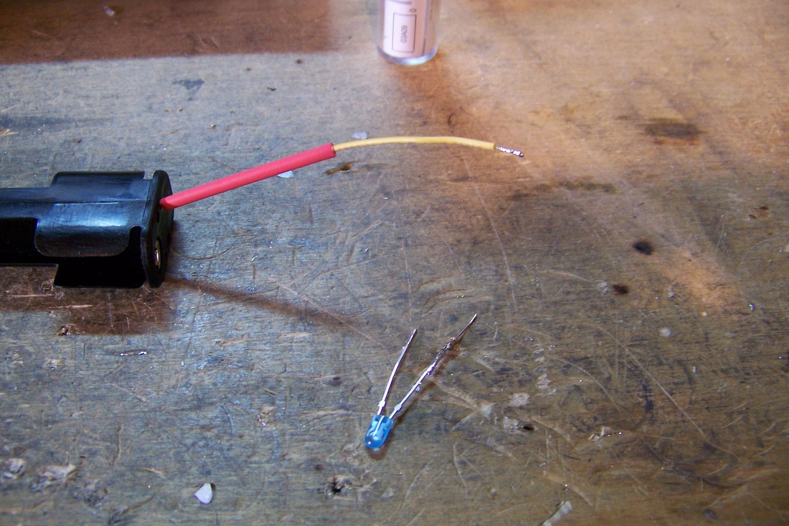
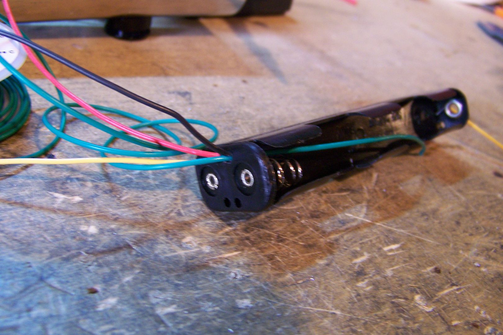
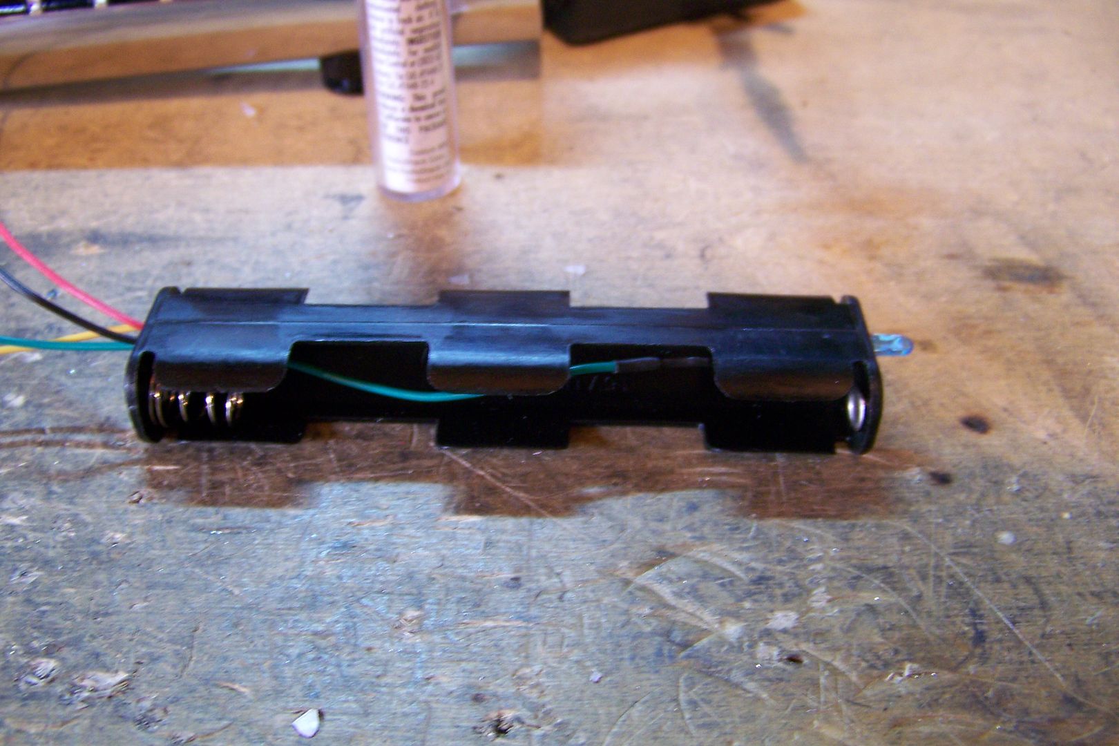
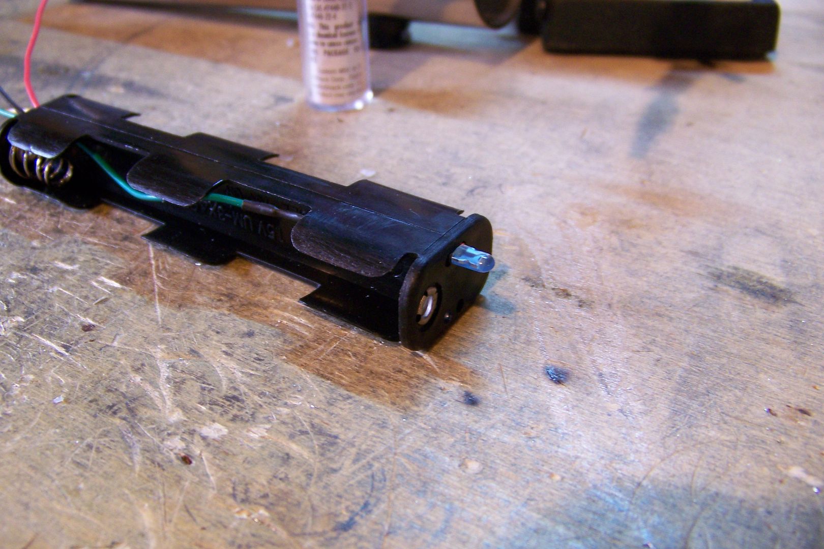
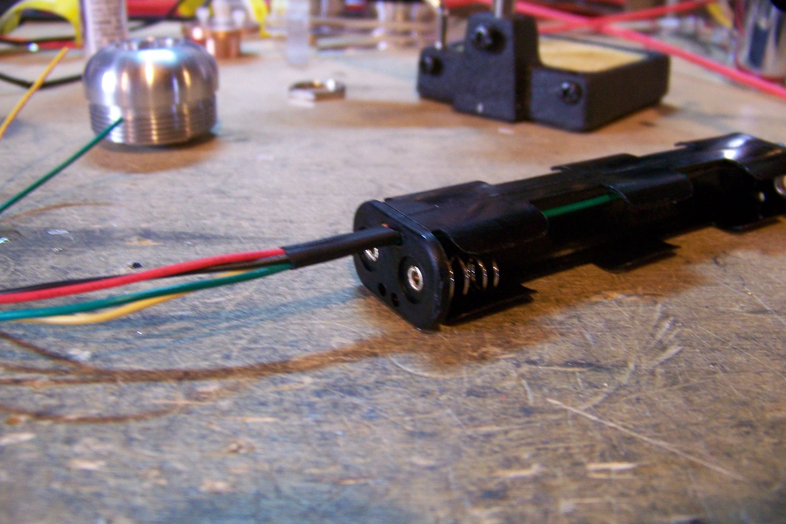
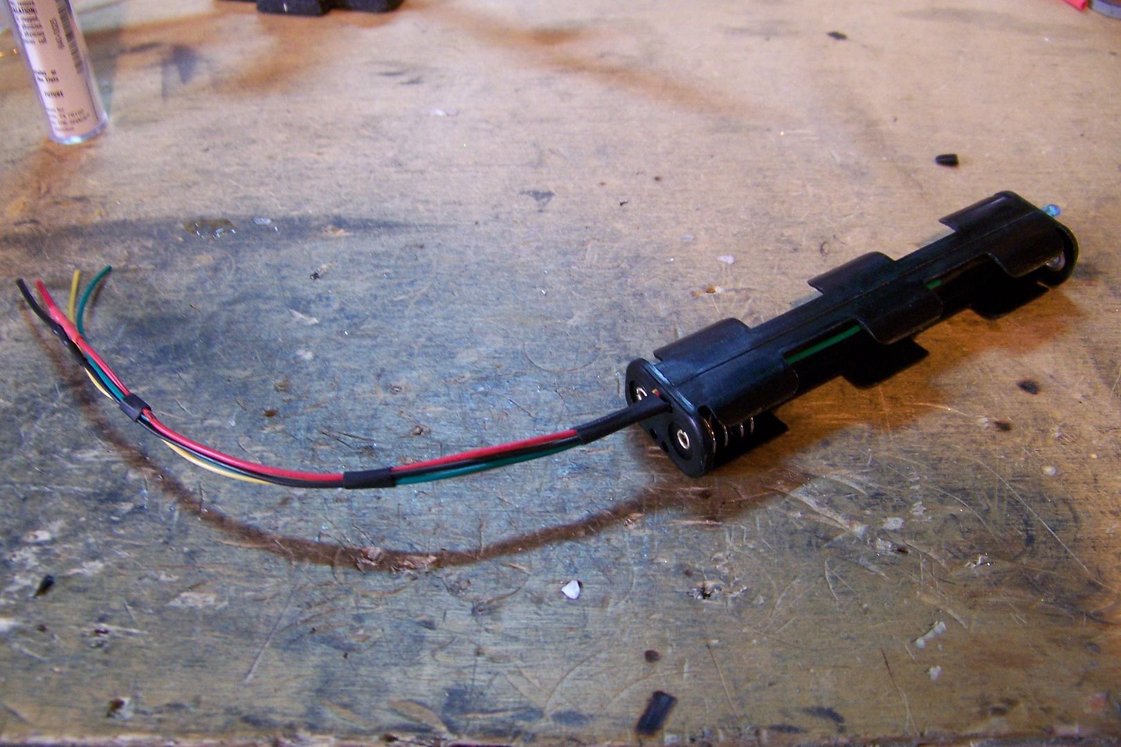
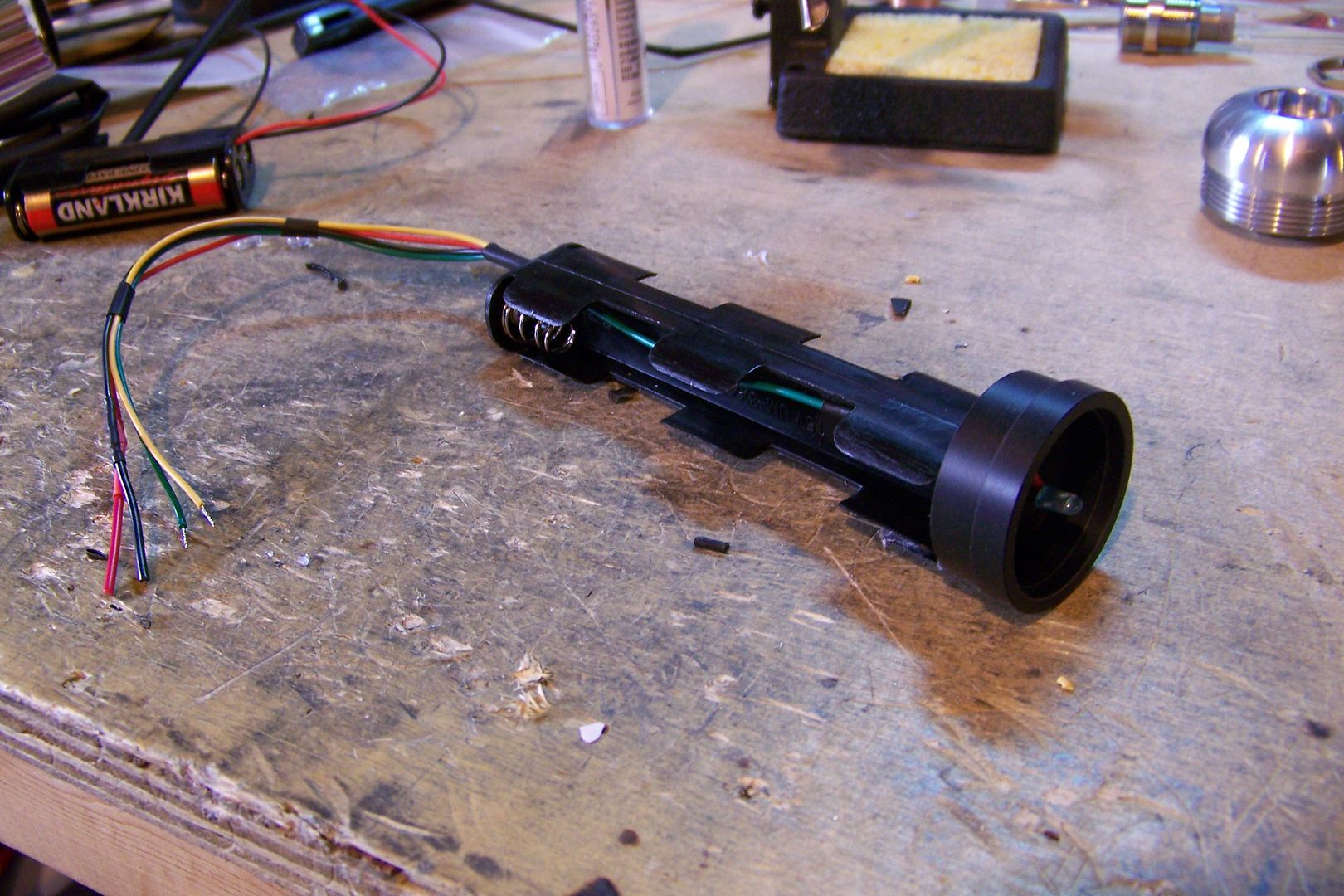
      4 AA (6v) battery pack
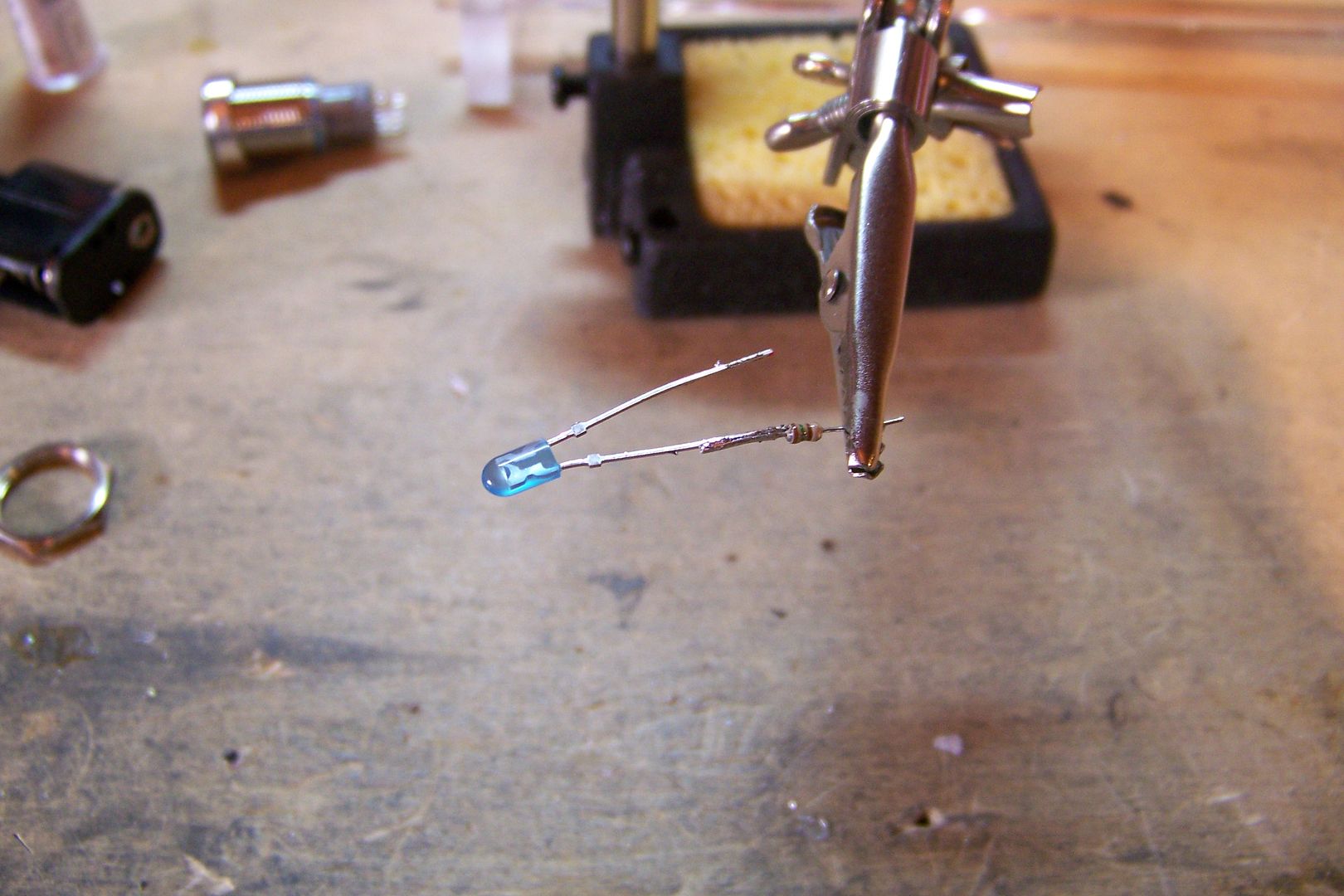
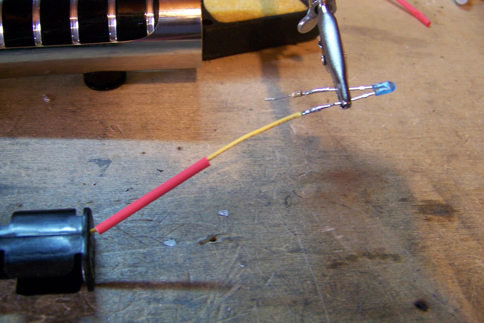
      Seoul P4 blue led
      5 degree lens
      Luxeon III lens holder
      3.3ohm, 3watt resistor
      quick-disconnect plug


    This saber shouldn't take too much too long to build! I got started on it yesterday by cutting the chrome sink tube to length, and as soon as I cut it, I realized I had goofed....I measured it wrong so it was un-useable. I had wait until today to go to the hardware and get a replacement for it.

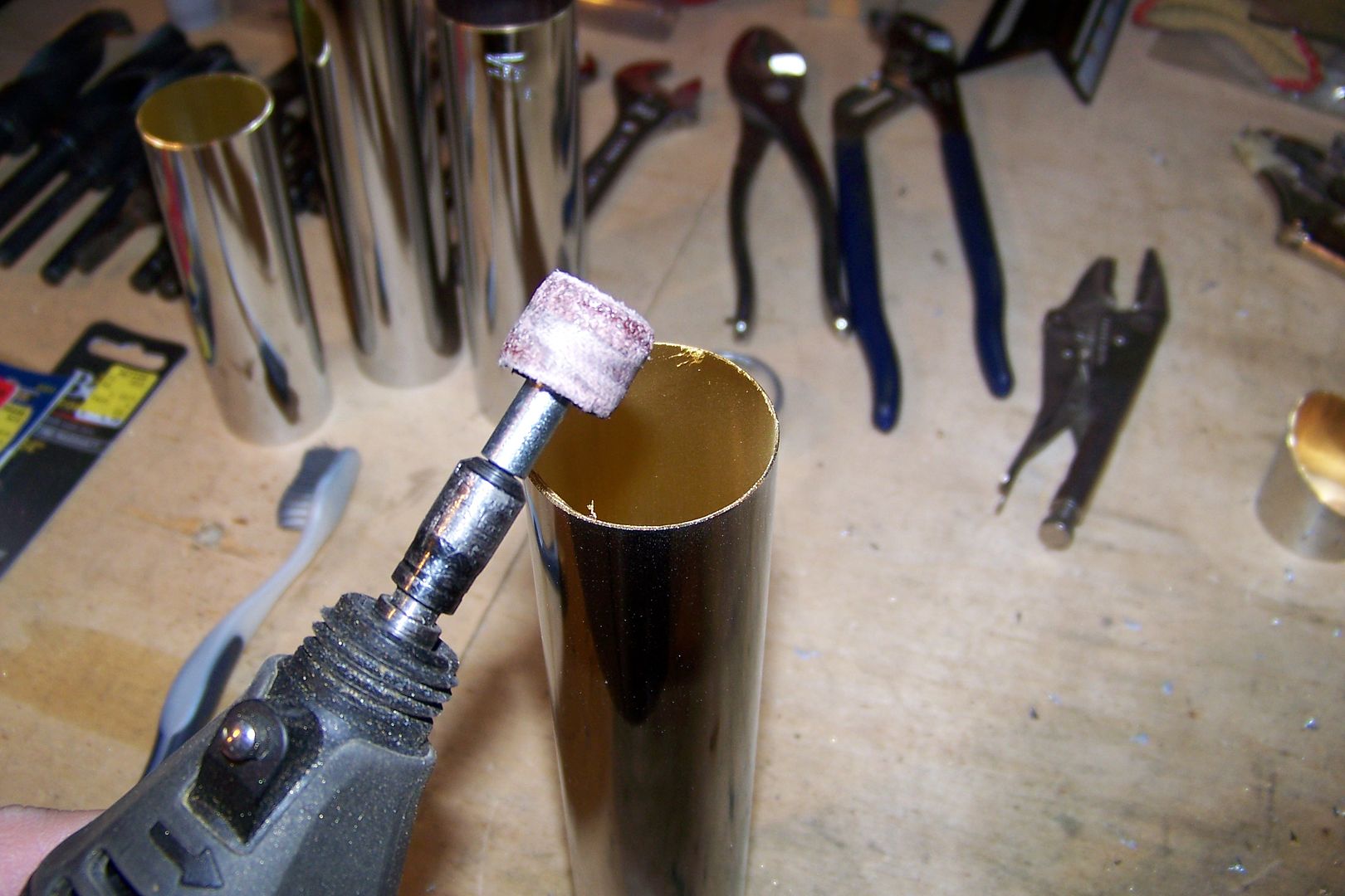
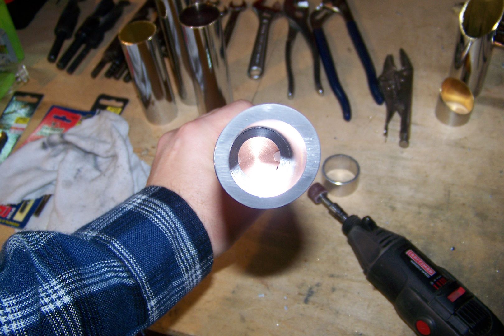
    So, after screwing up the first chrome tube I cut for the half sleeve for this saber (I measured it at 6" instead of 7"....D'OH! ) I cut the new one to length and used my rotary tool to de-burr the part:


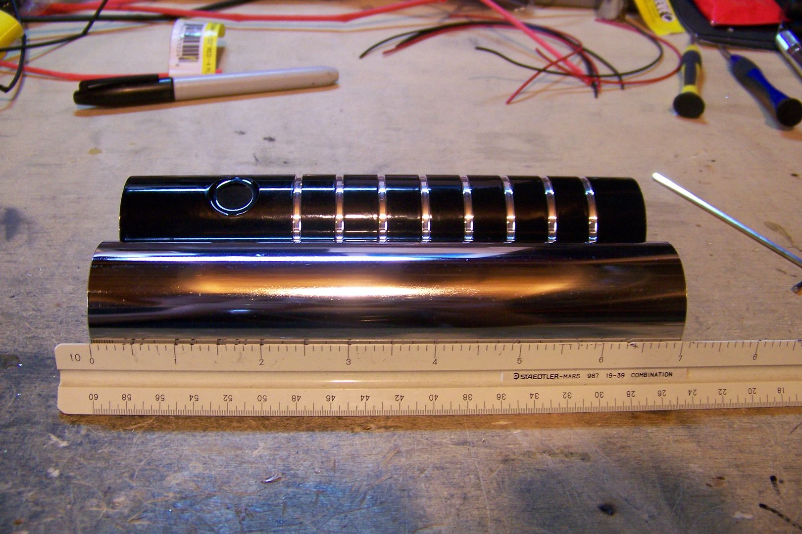
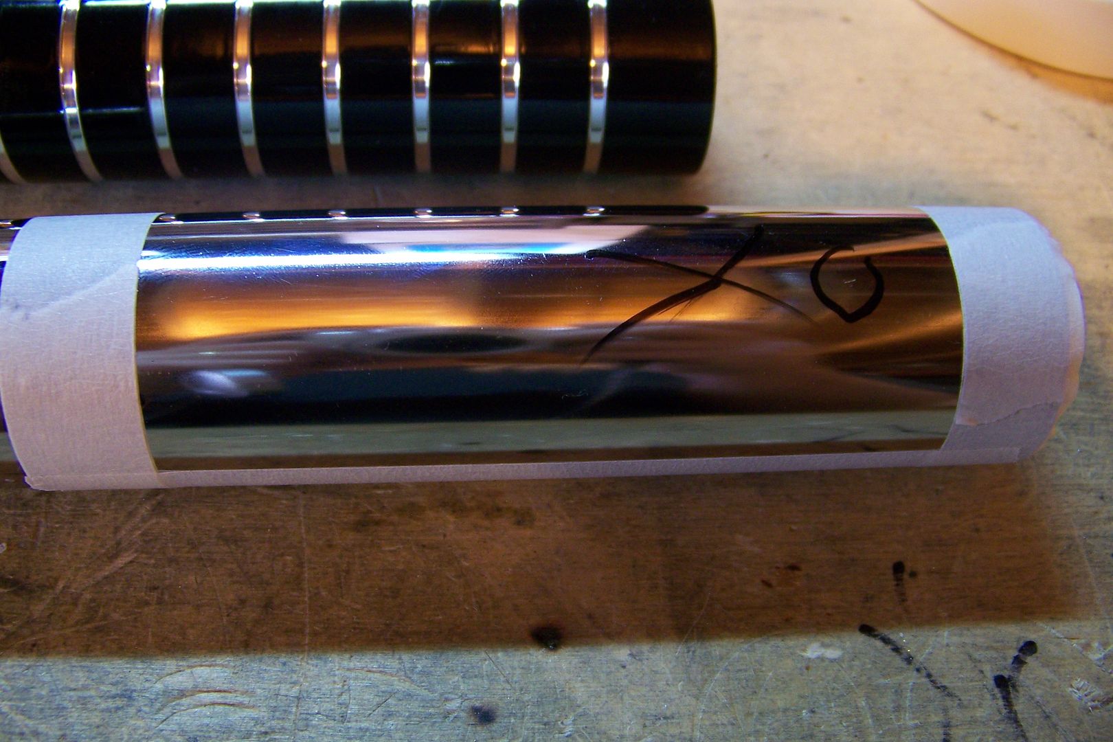
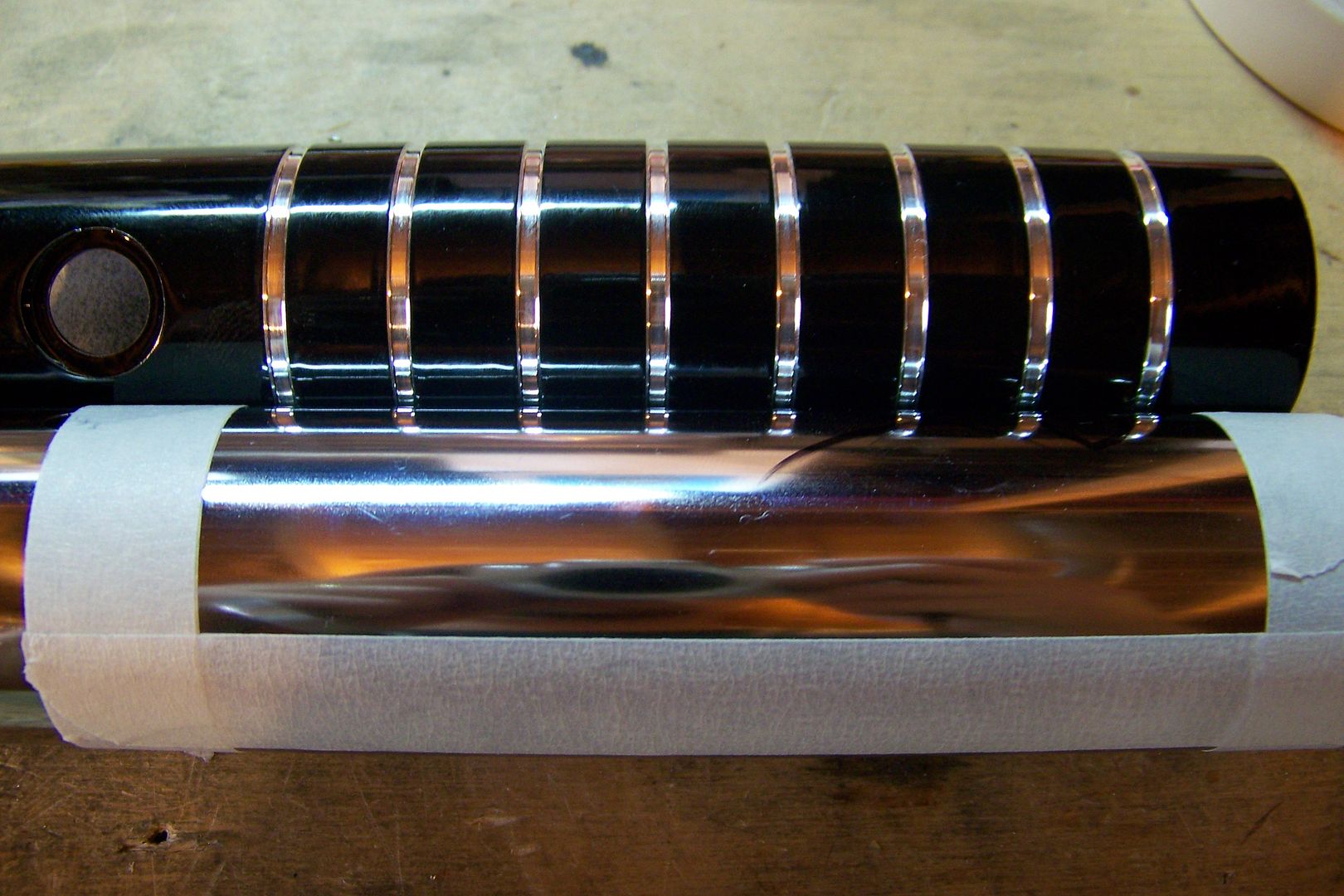
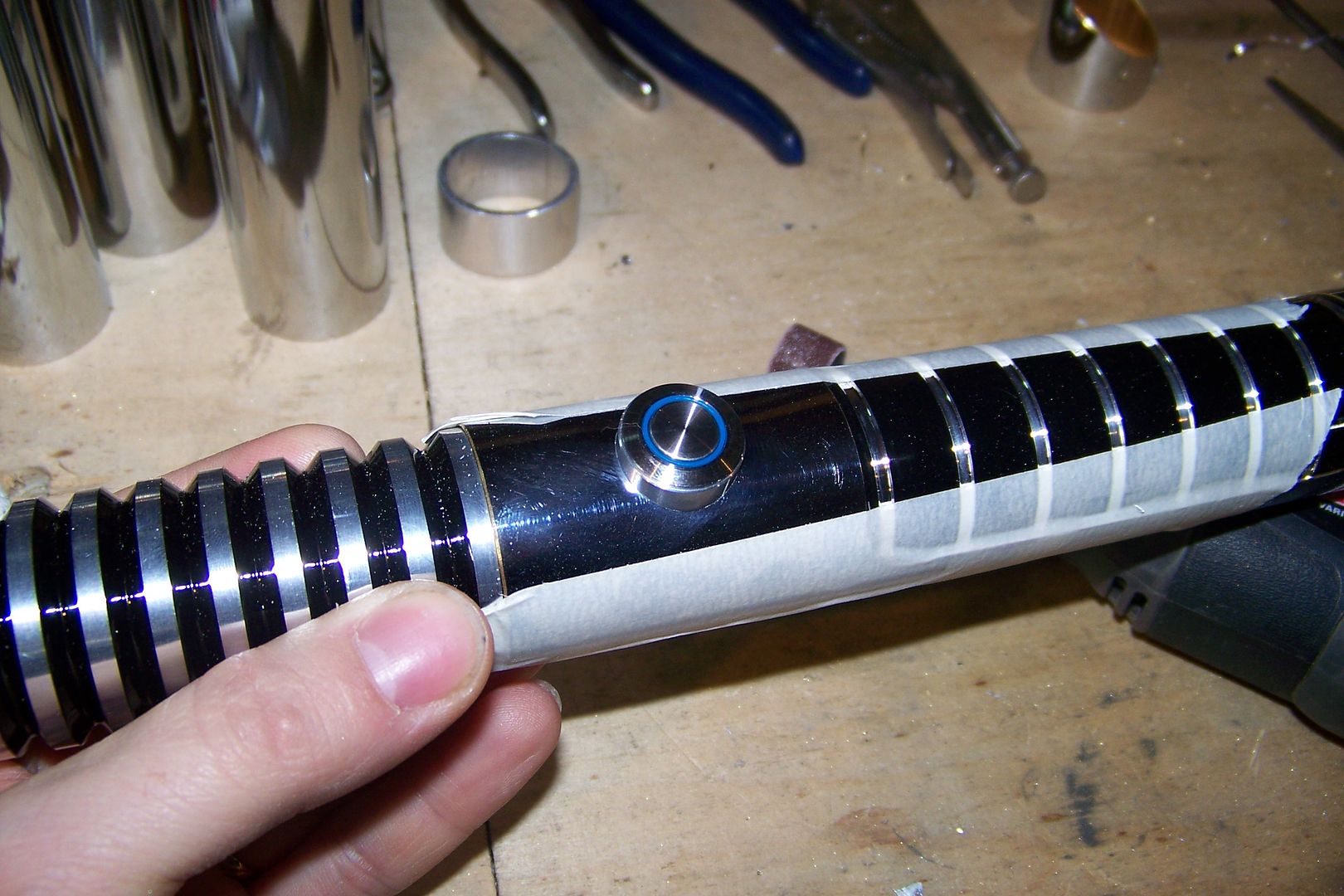
    With the sleeve deburred, I laid it out next to the hilt and checked to see where I'll have to cut it for the grip window:


    I then marked it off using a black Sharpie:


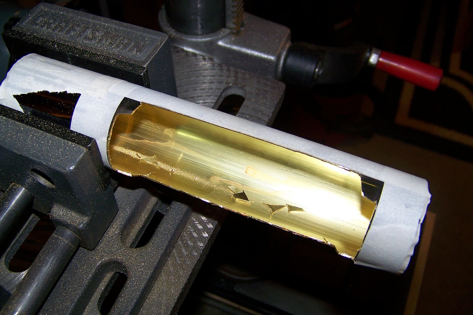
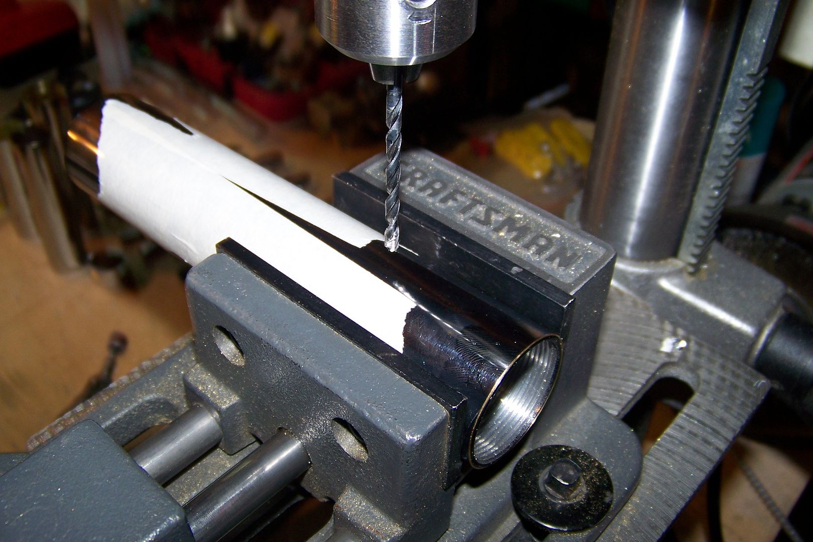
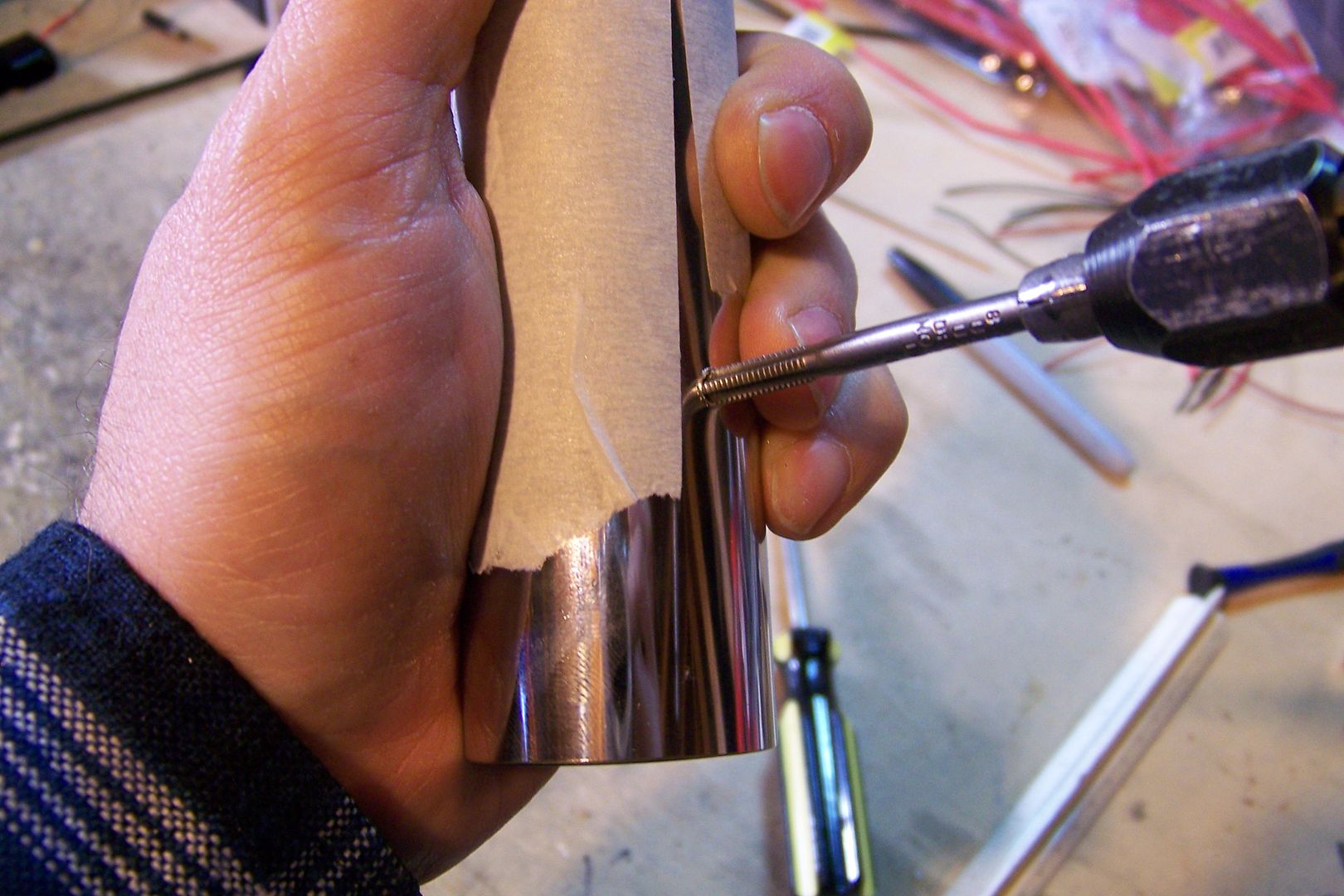
    And using masking tape, made the pattern I'll follow with the cutting disc on my rotary tool:


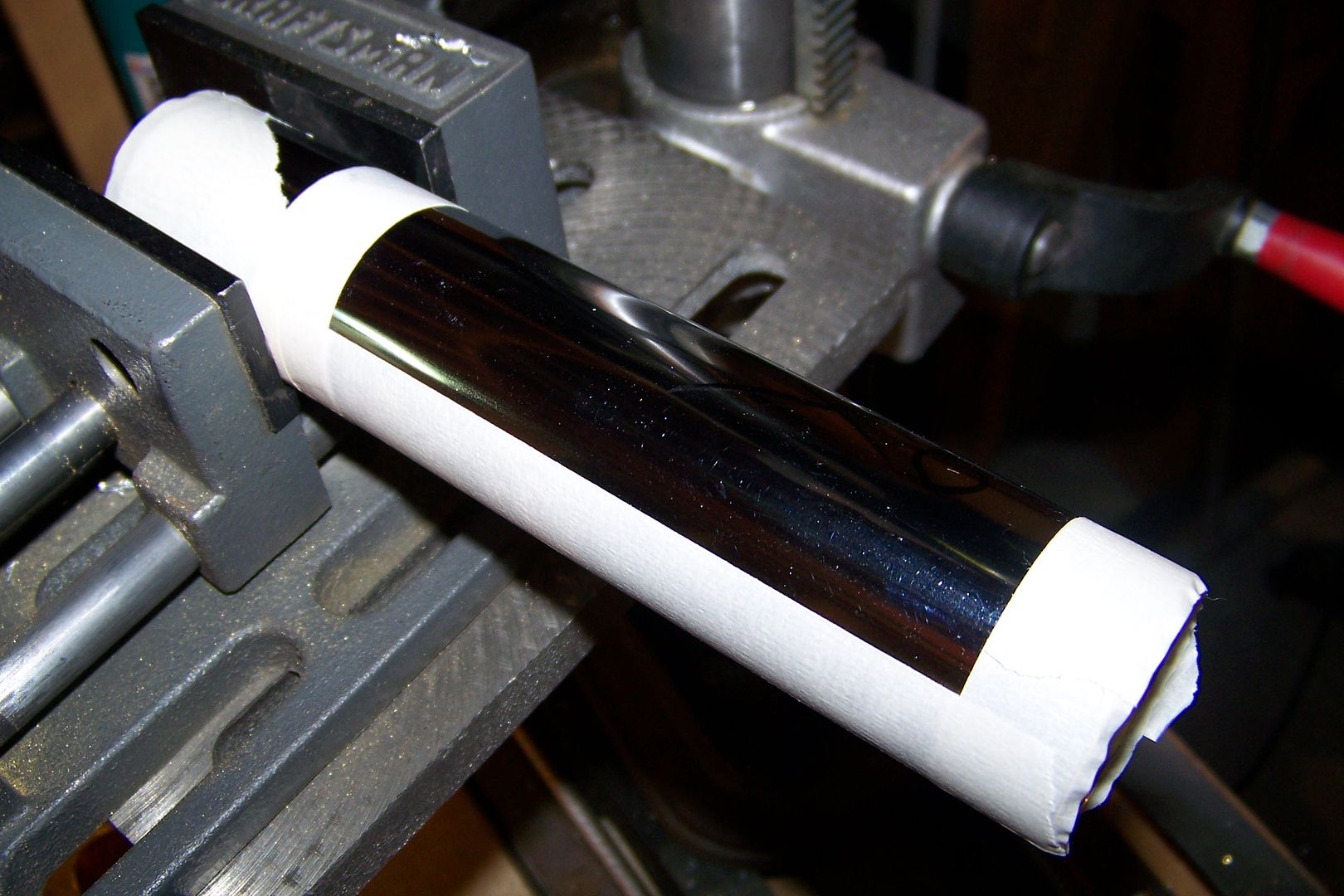
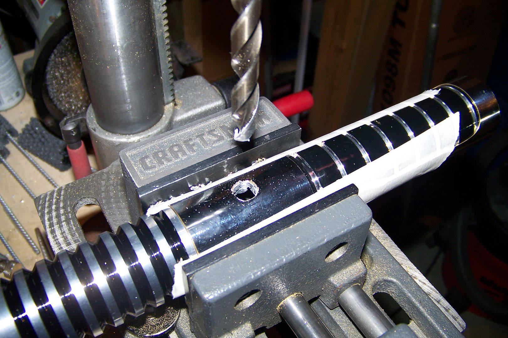
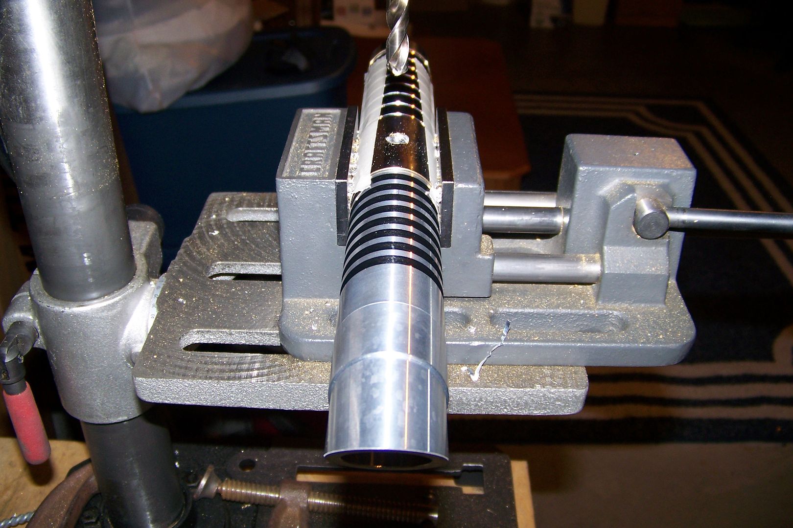
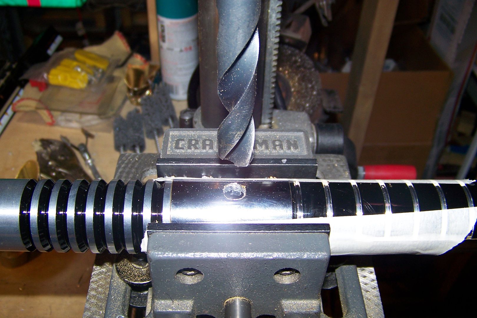
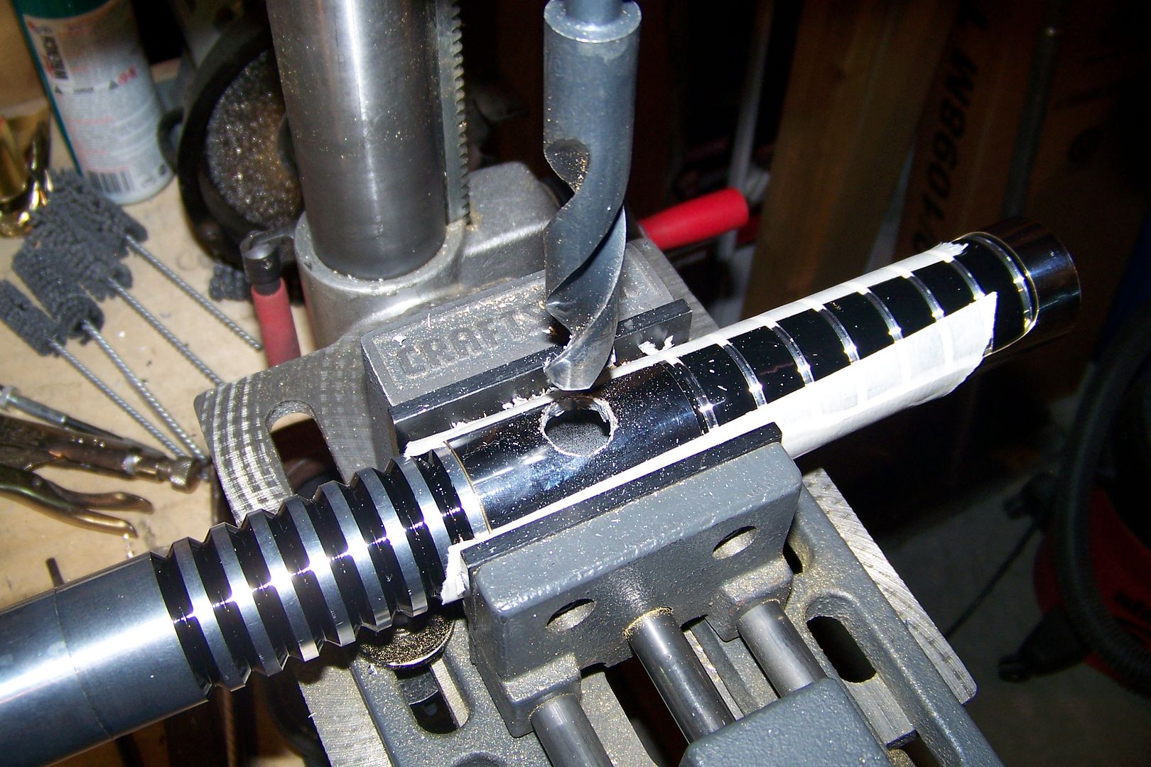
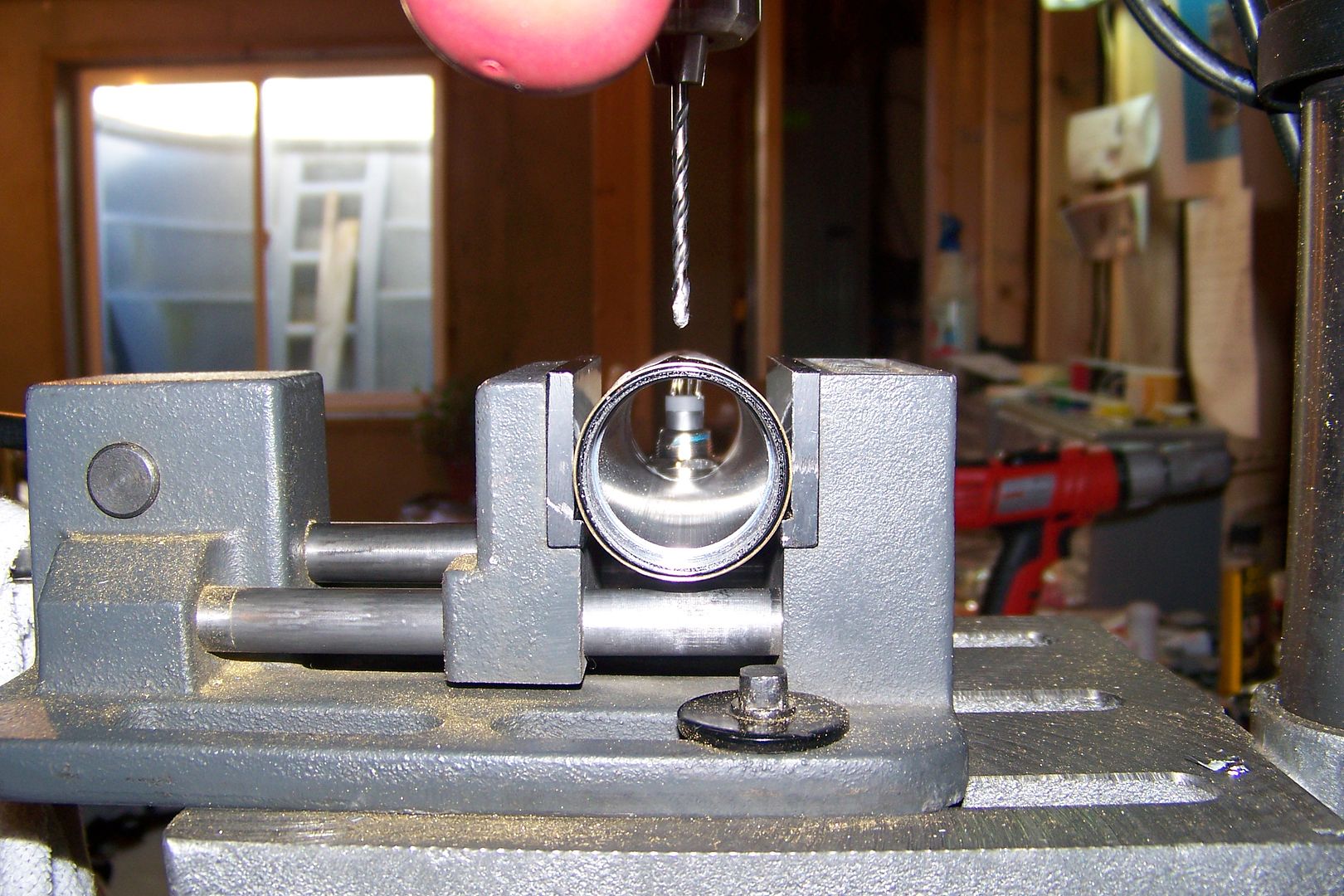
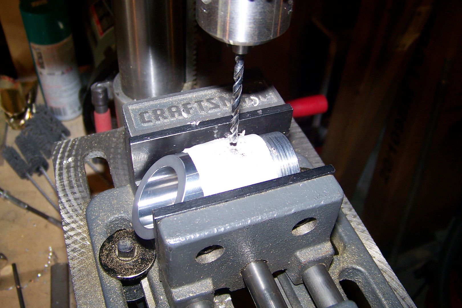
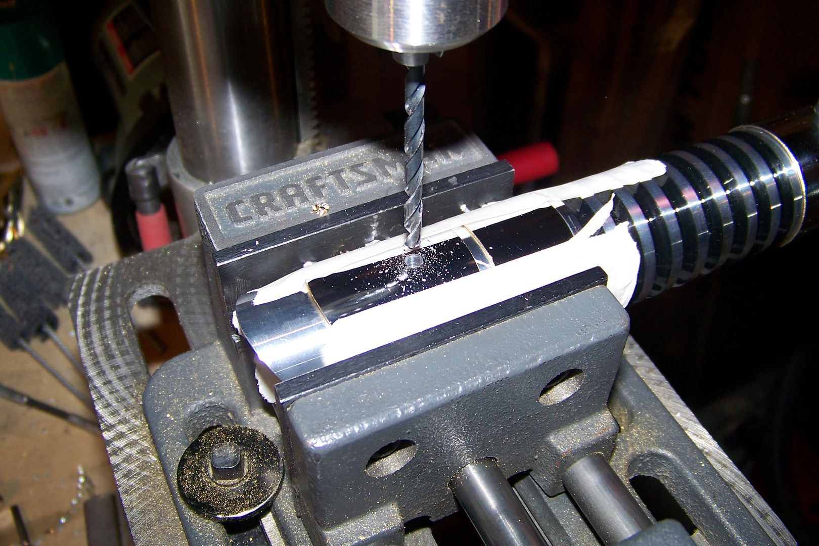
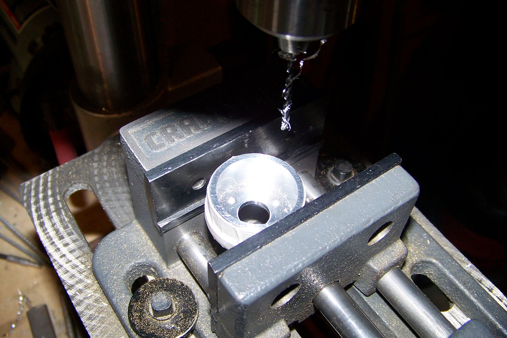
    I set it up in my drill press's vise:


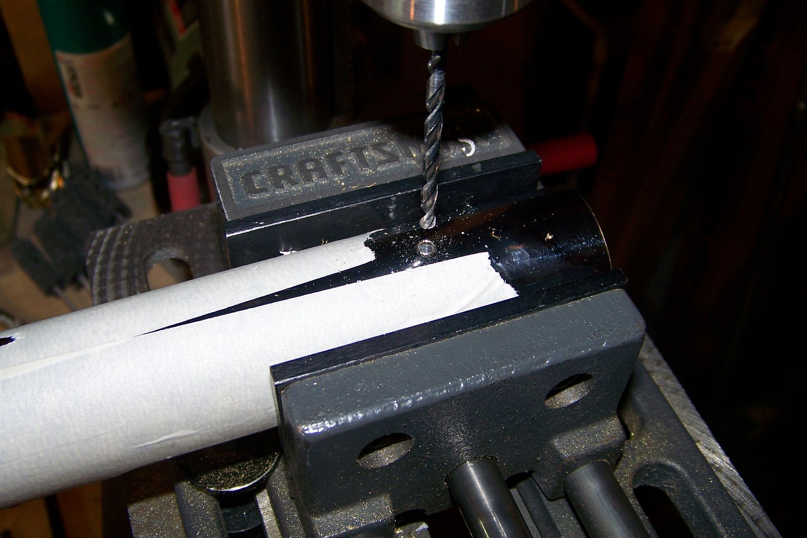
    And started cutting:


    I always follow the direction of the cutting wheel, so in this case, I had to move from right to left to make these cuts:


    To remove the un-needed piece, I'll cut across the corners at an angle:


    The black thing in the corner of this picture is the end of my shop vac's hose:

    I use it as a dust collector when I'm cutting tubing....helps keep the mess to a minimum, and I breathe less dust that way. I also use a dust mask and safety glasses, as well.

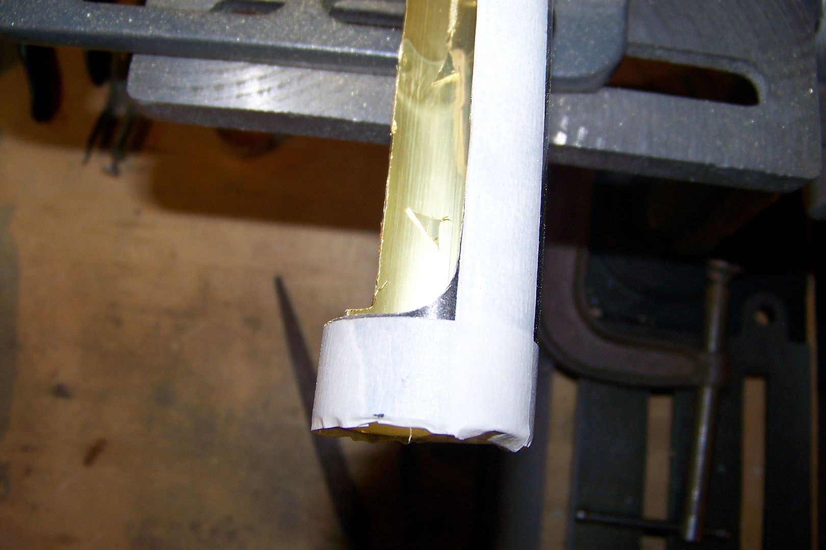
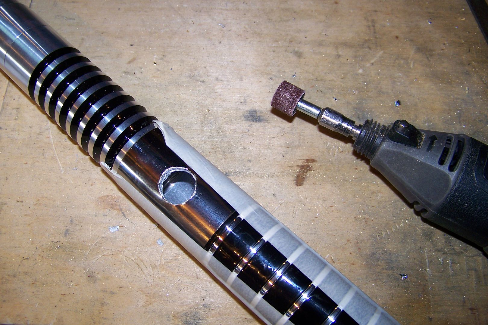
    There's more material to remove from the corners, so I'll continue with the cutting disc on the rotary tool, and just get what I can with it:


    Done with the cutting disc:


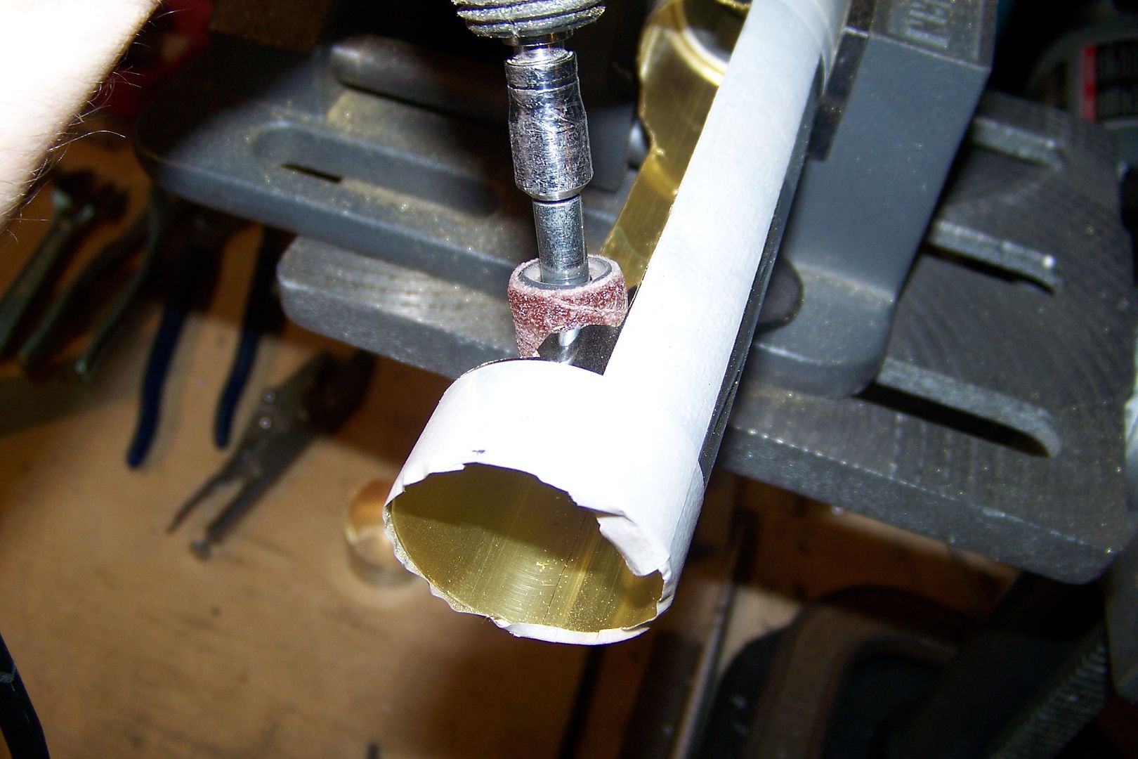
    I'll change the disc out for the 5/8" sanding drum attachment so I can round out the corners:


    I use an oscillating motion when I do this, to even the wear on the sanding drum. Otherwise, I'd get a single worn strip on the drum, and eventually a cut. Work the drum into the corner until all the material is removed, and you have a nice rounded corner:


    I did all four corners:


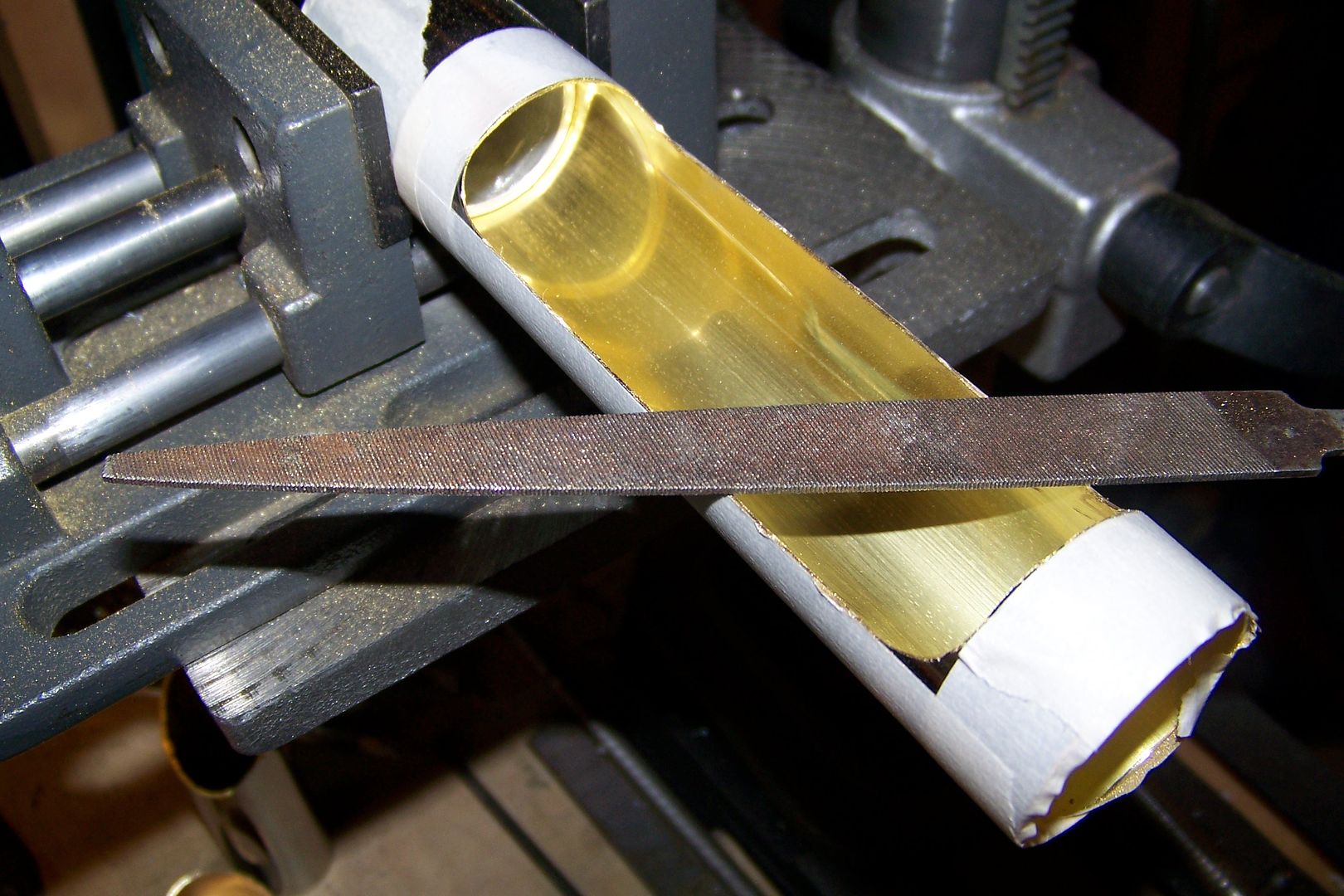
    To further straighten the edges of the window, I'll use a hand file for metal:

    This may require the removal of extra material depending on how steady your hands are when you cut the window out, and how straight your cuts were. I had to go back to the rotary tool with the sanding drum to even the corners out again after I was finished filing.

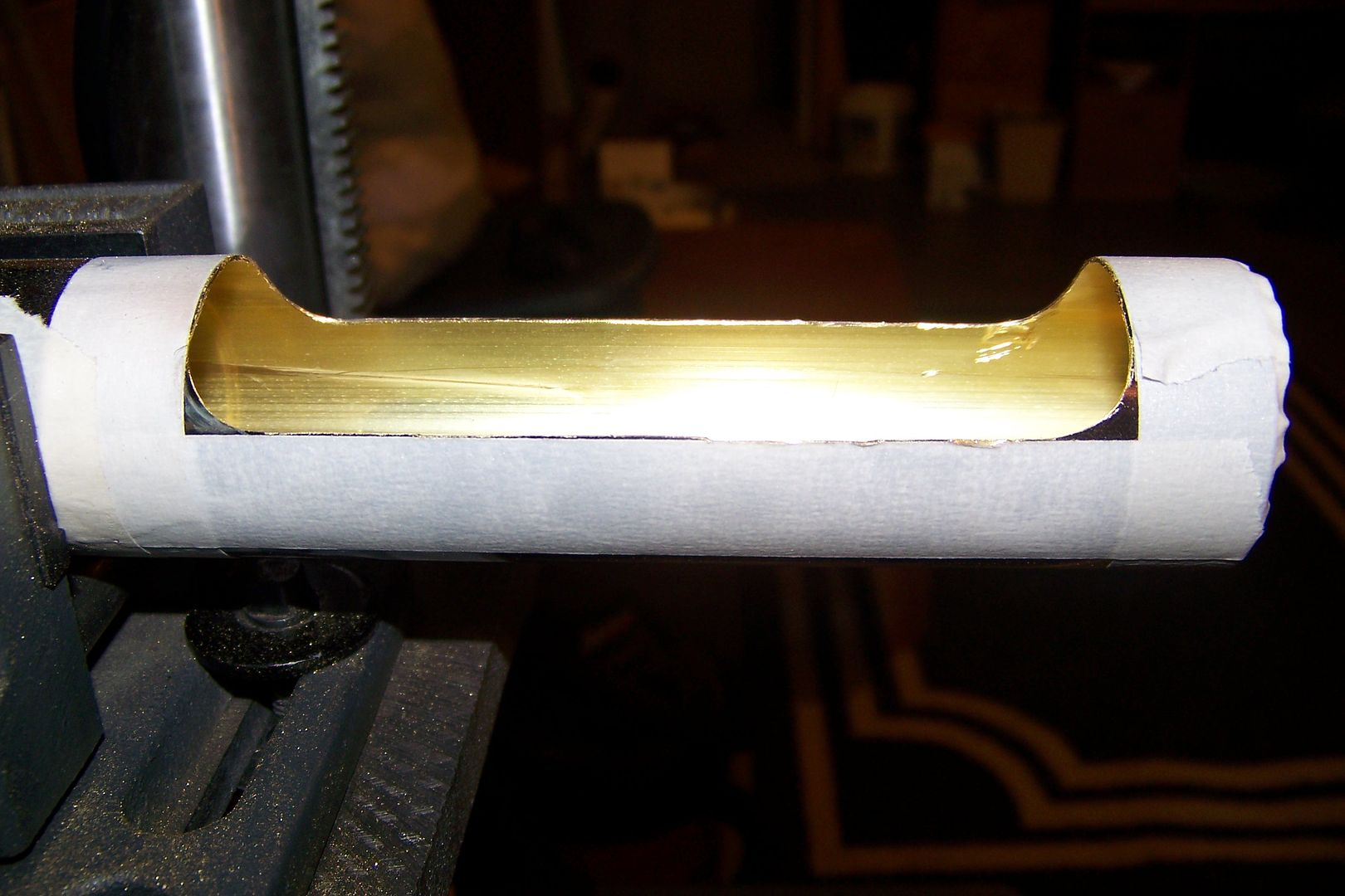
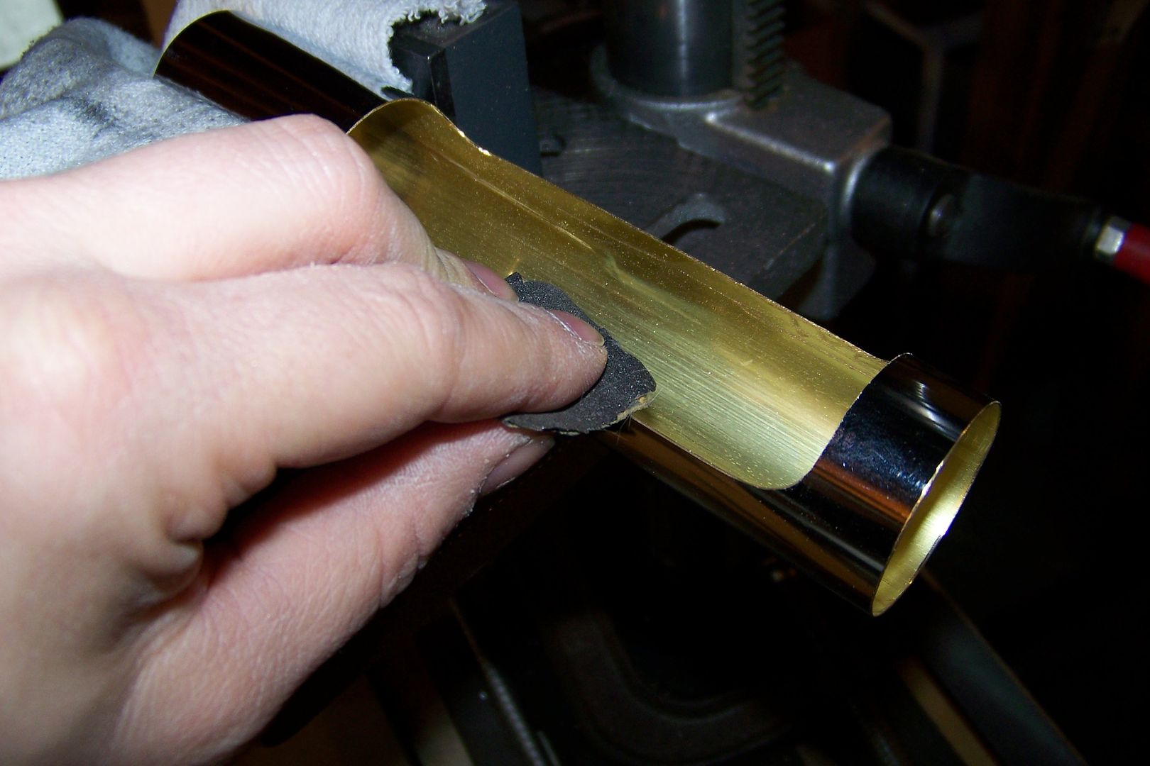
    With the filing done, and all the edges looked straight, I went over the widow's edges again by hand with some 400 grit sandpaper:

    After that, I went over it again with a piece of 800 to really smooth it out.

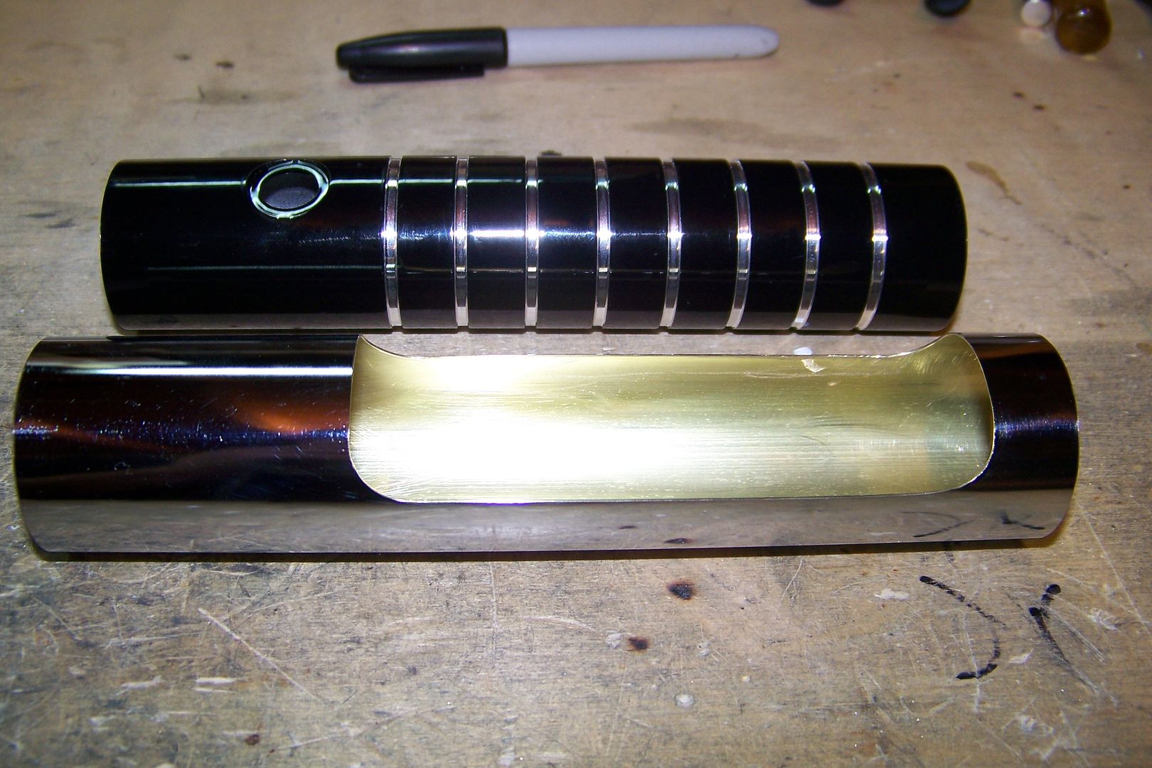
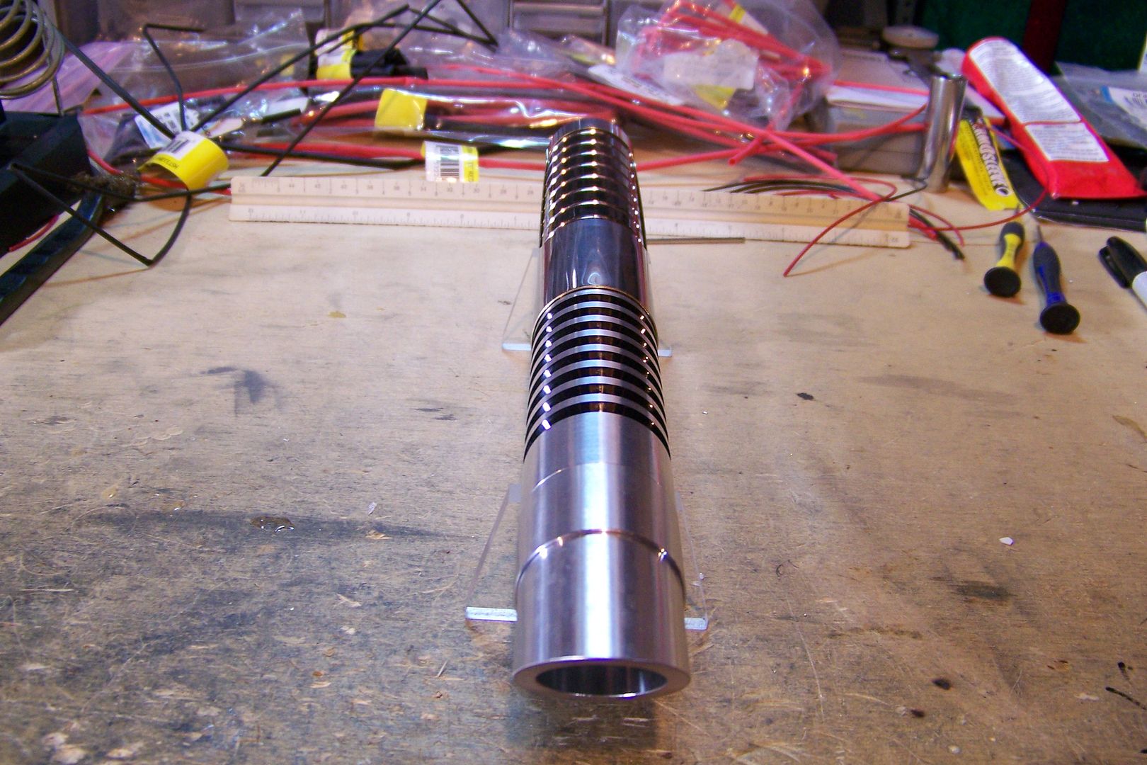
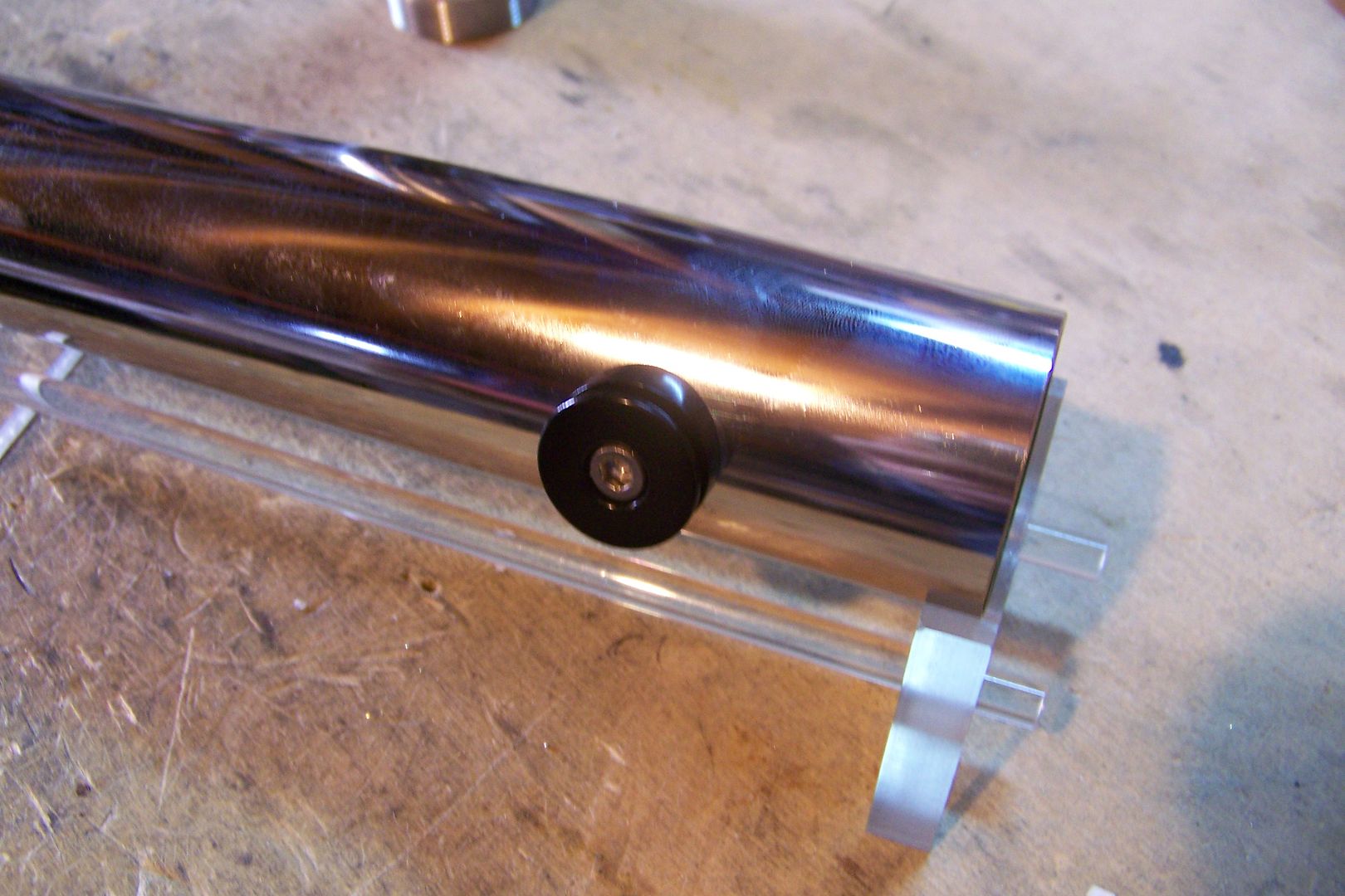
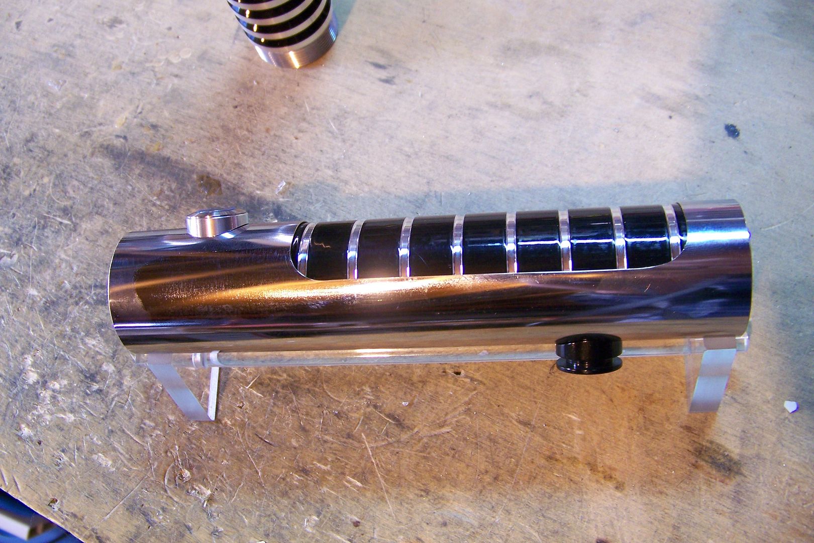
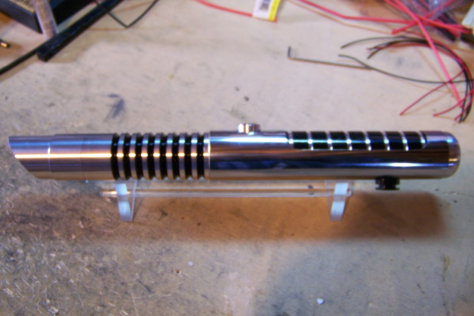
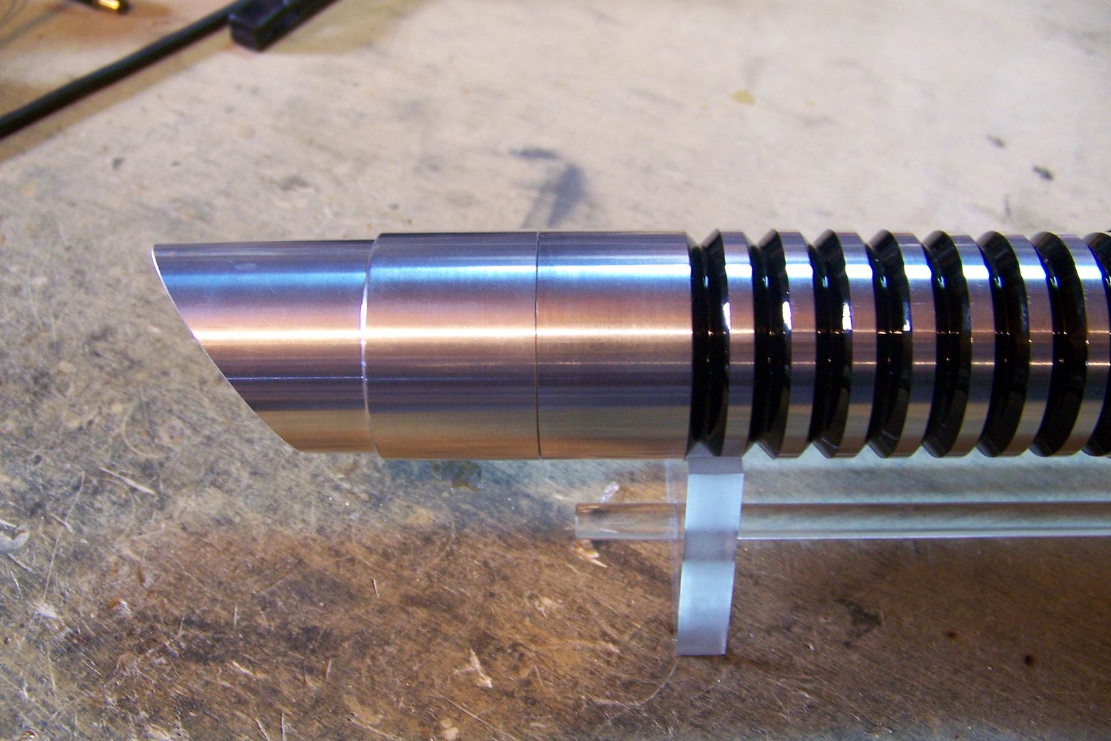
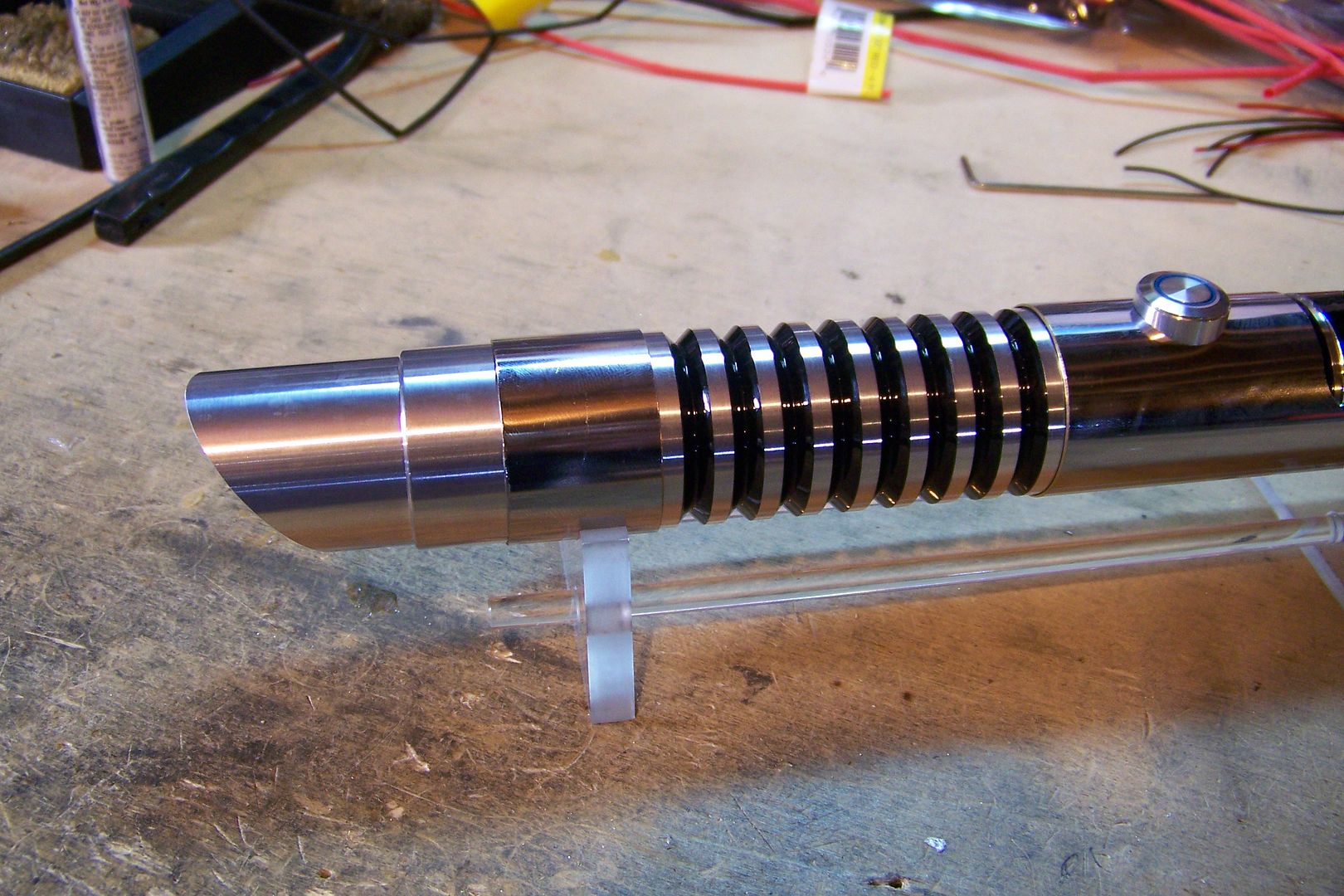
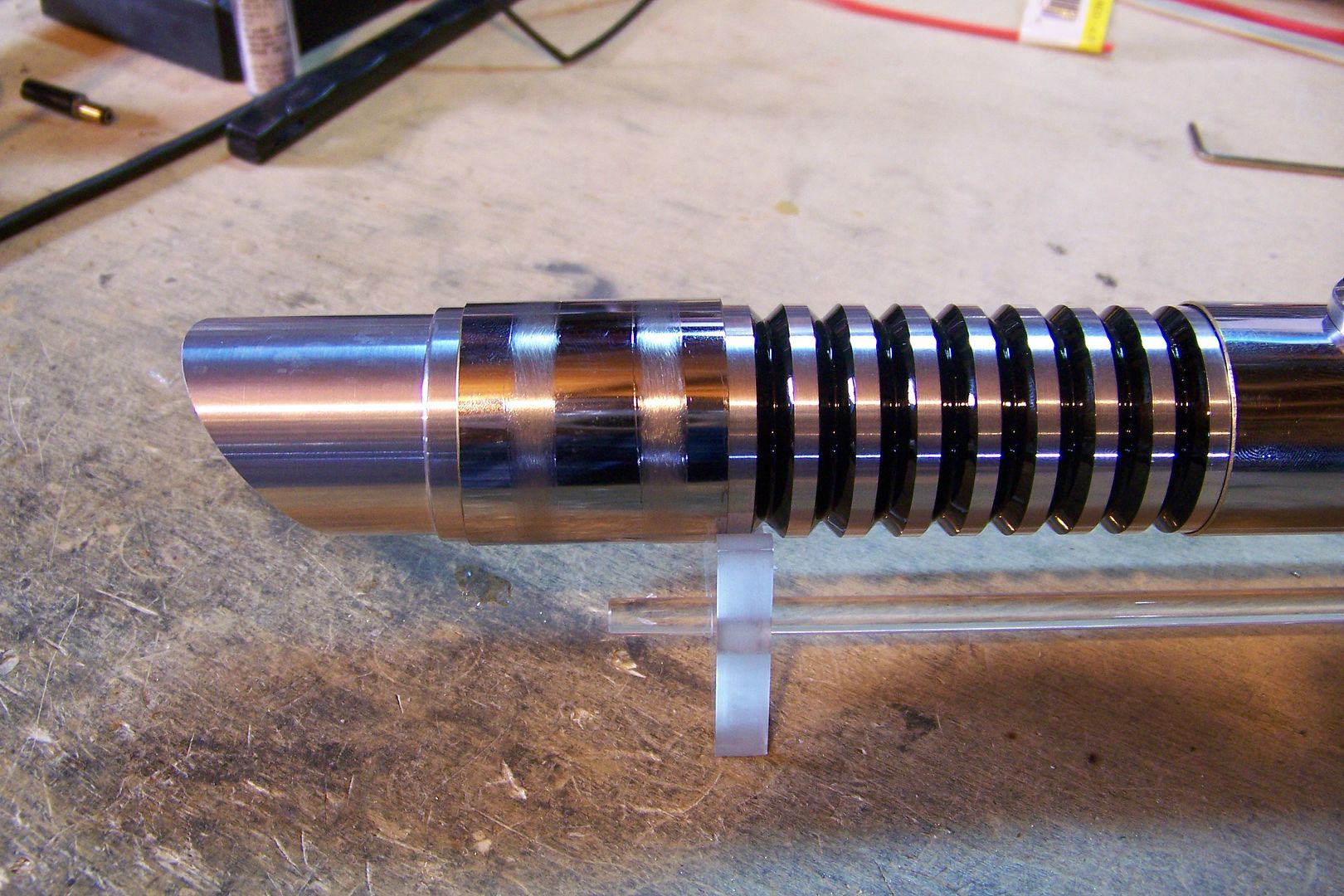
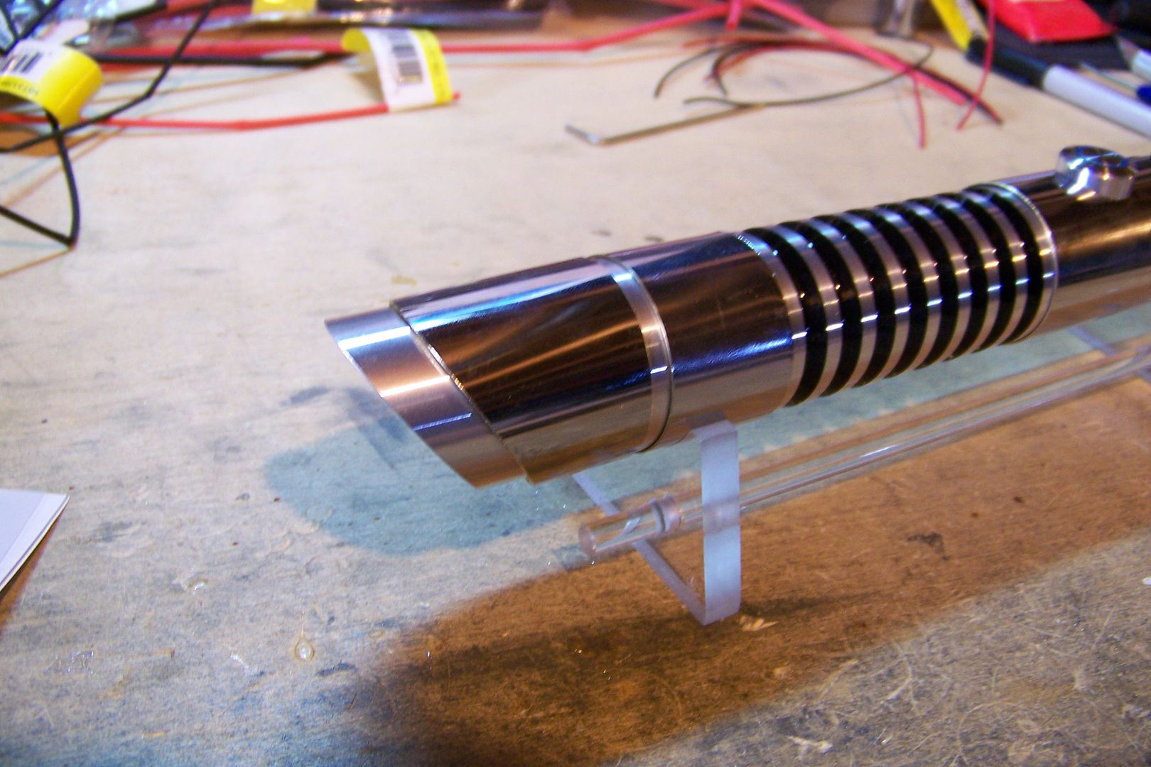
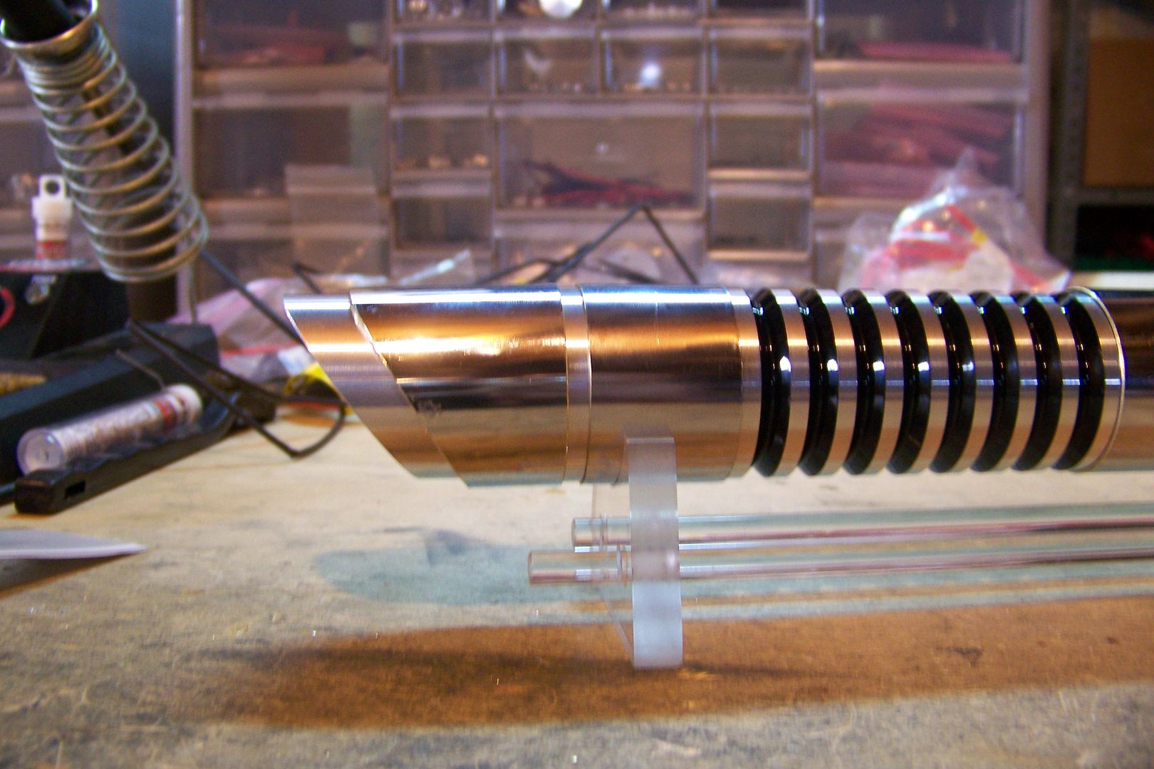
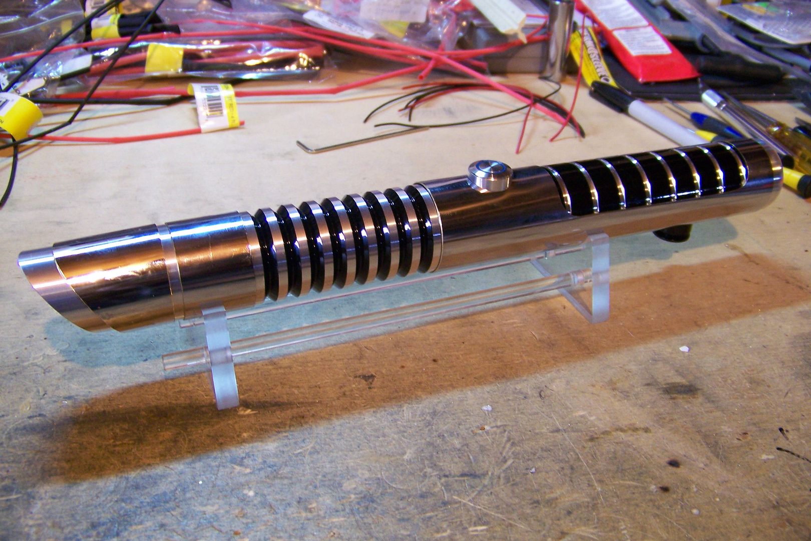
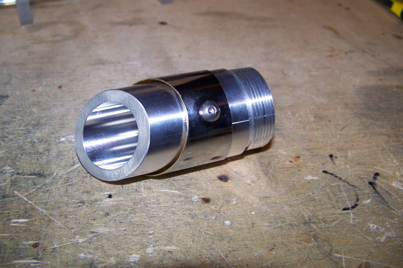
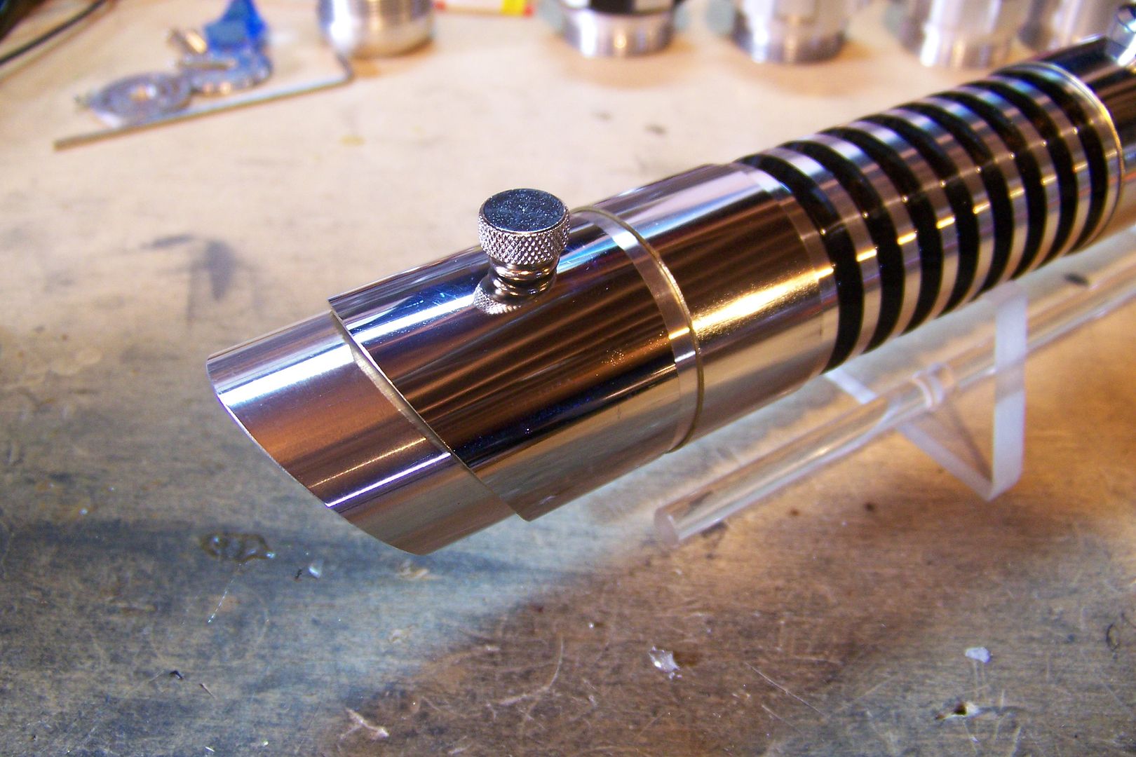
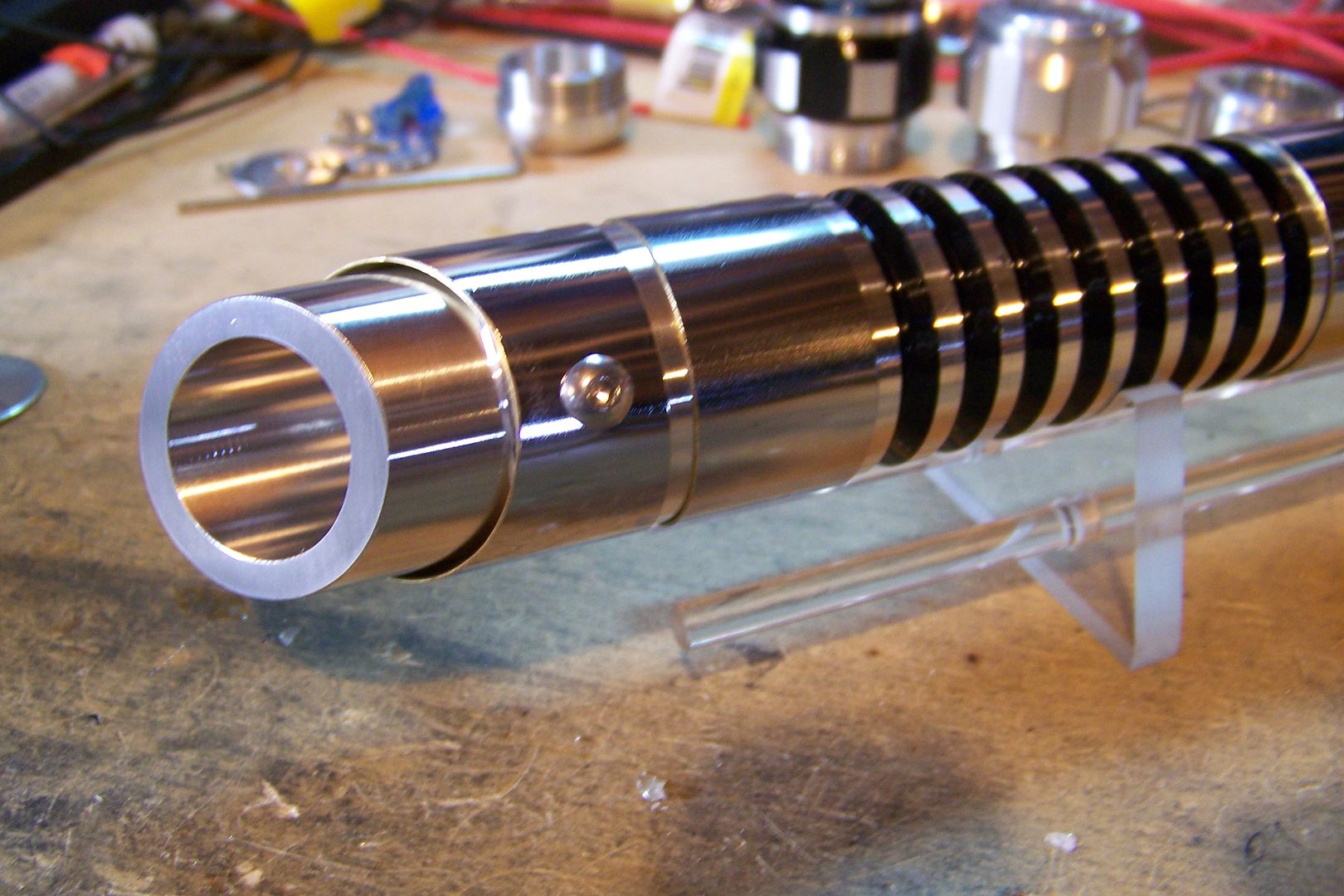
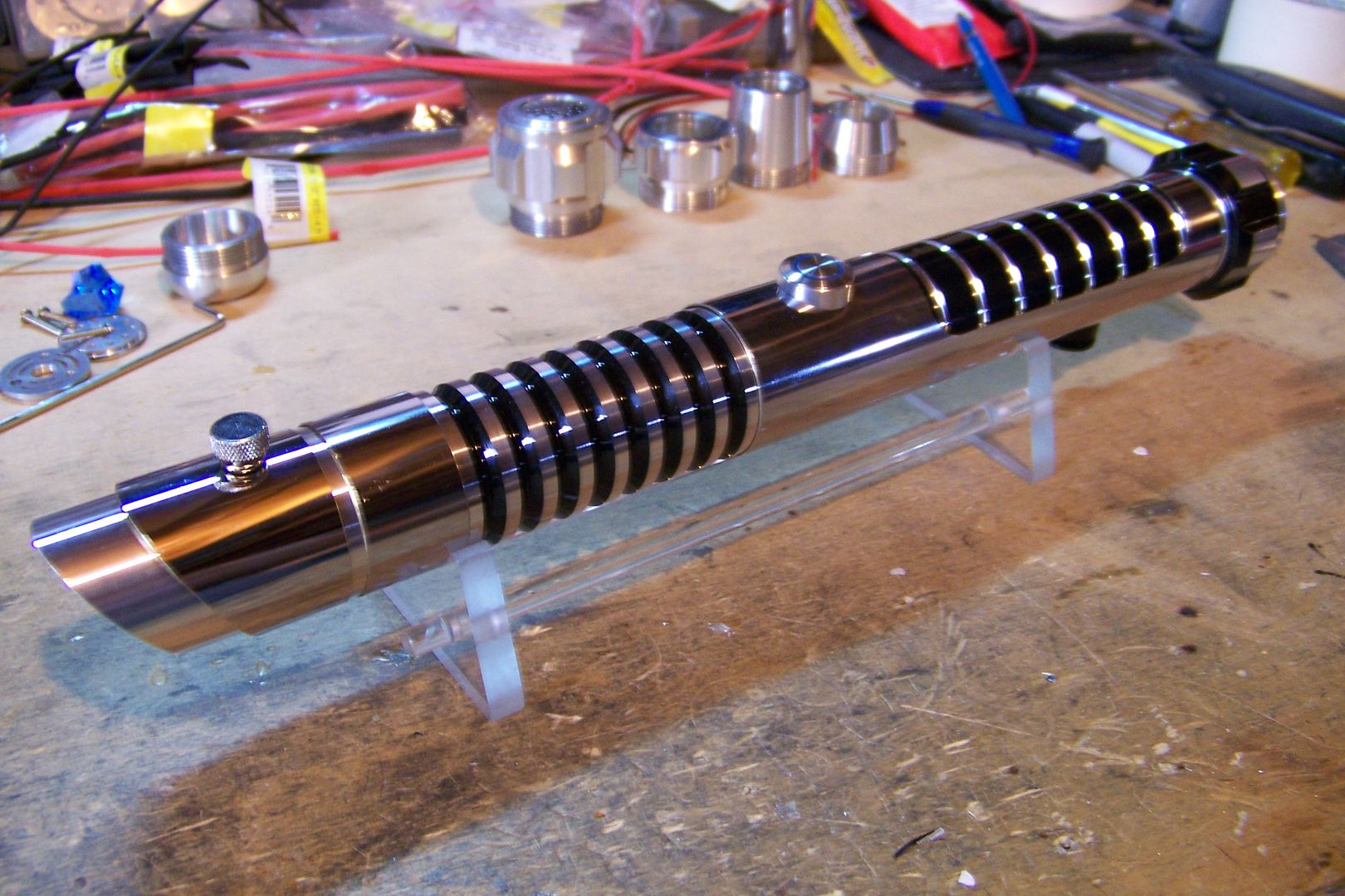
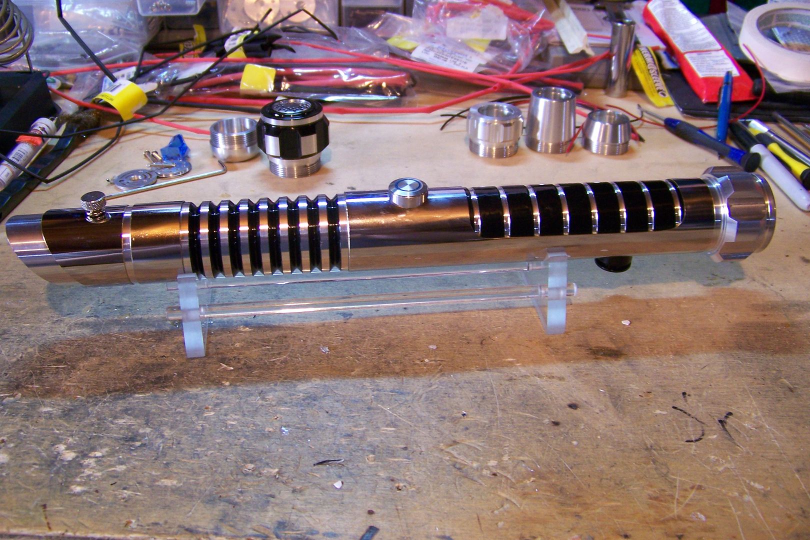
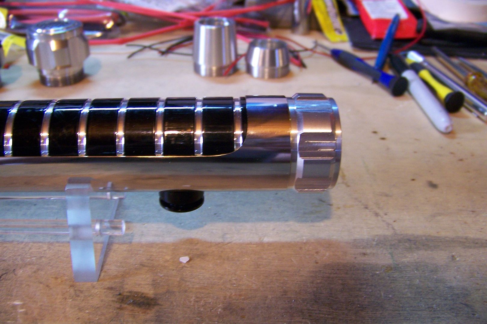
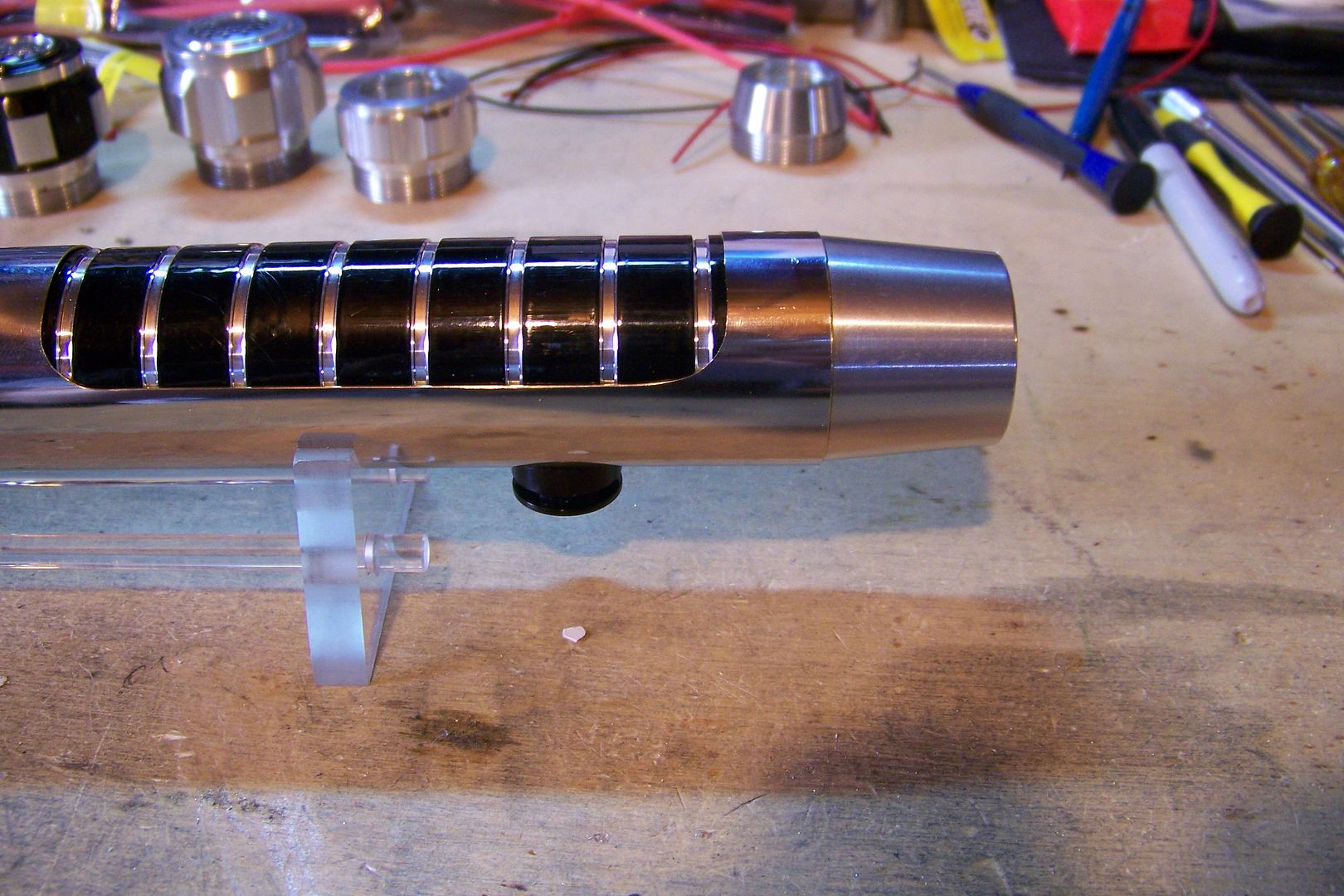
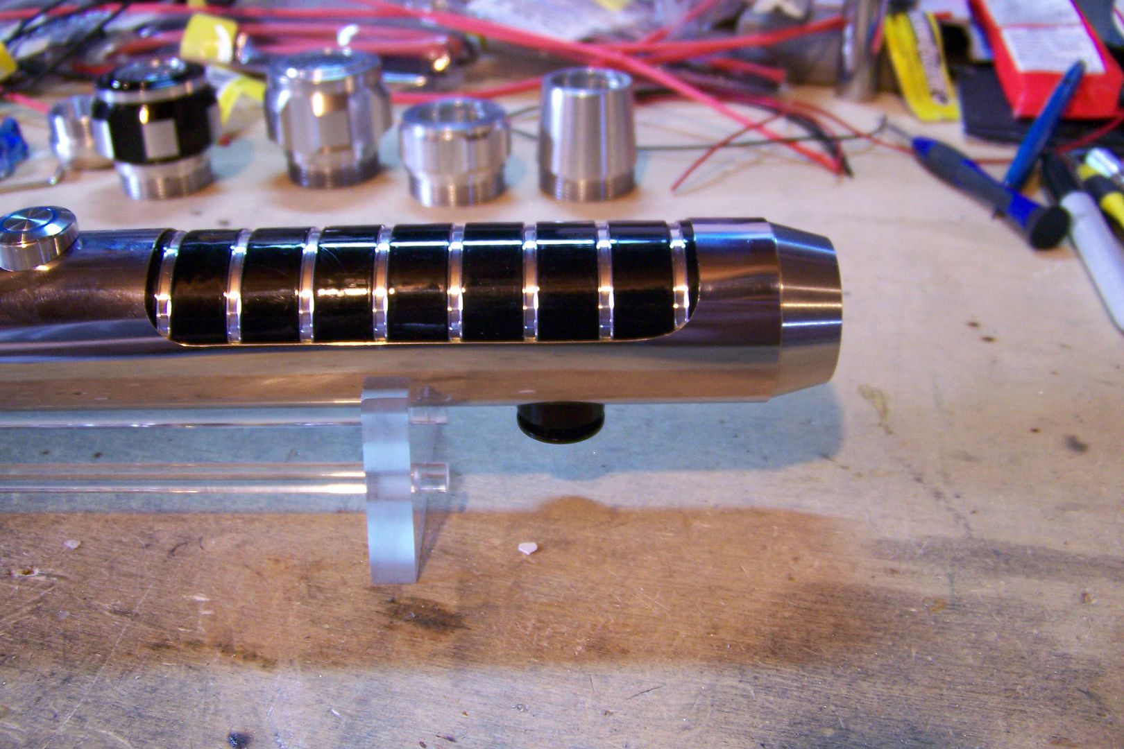
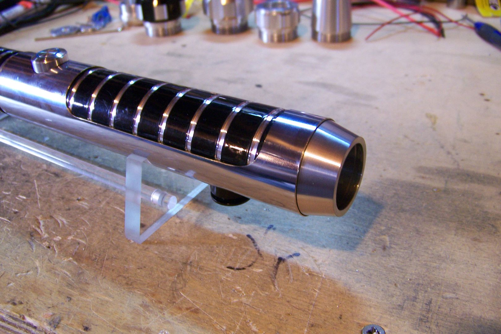
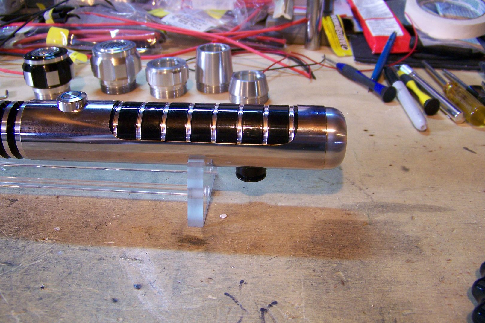
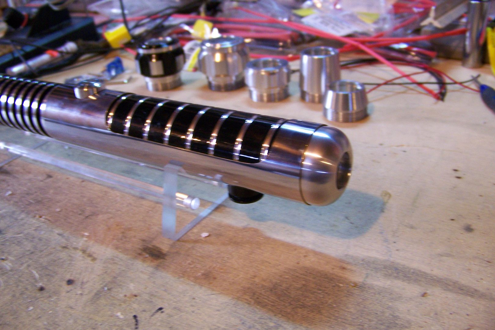
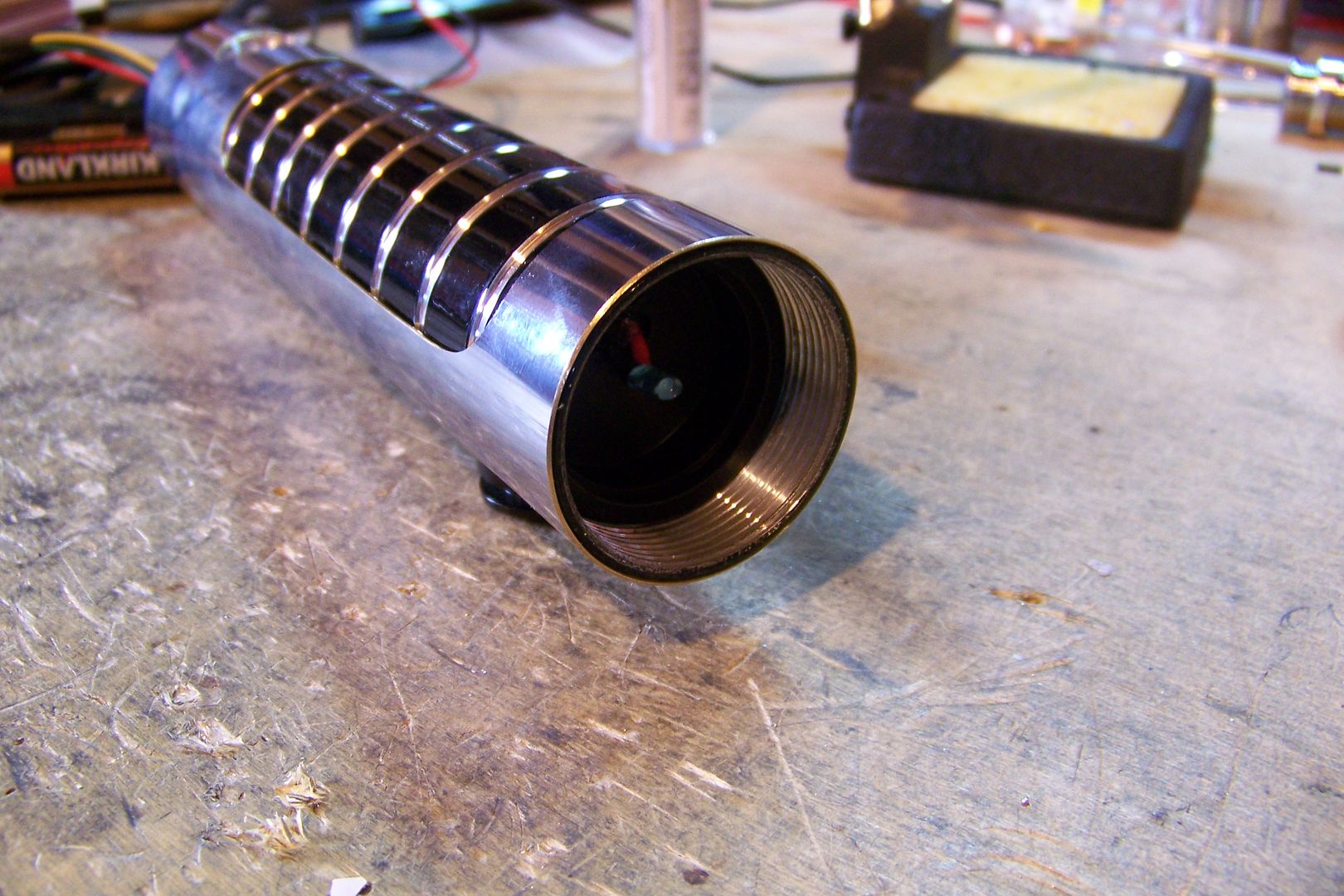
    Here's the finished sleeve with the hilt section:
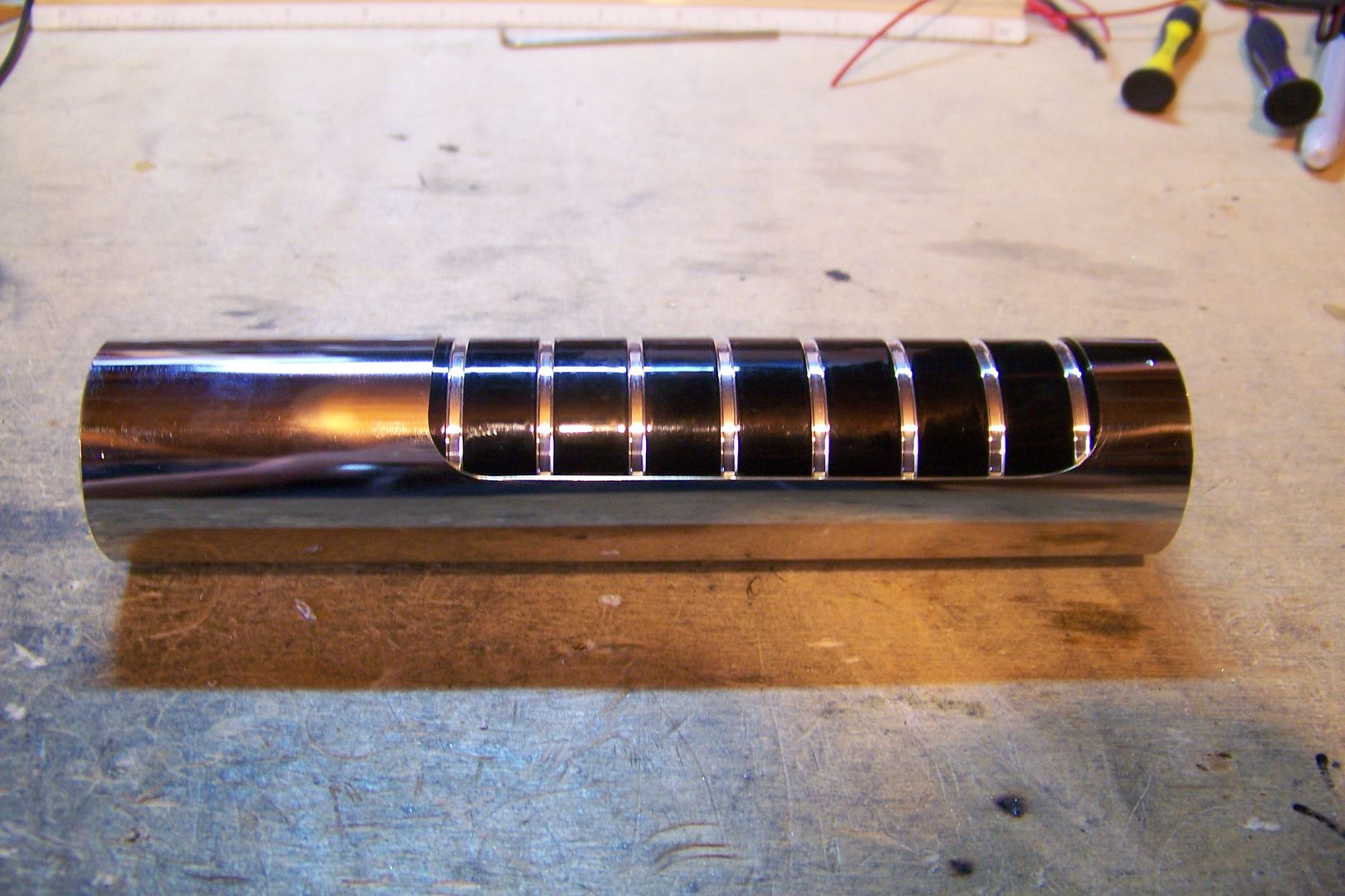

    And test fit:

    That'll work!
    Last edited by Jay-gon Jinn; 03-29-2010 at 09:47 AM.

    Got a question? Start Here. Have you tried the Thread Index yet? Most questions can be answered there.

  2. #2

    Default

    I like how you did the rounded corners.

  3. #3

    Default

    Great tutorial, Jay-gon. Now it seems kind of odd that no one (to the best of my knowledge) ever posted a tutorial on basic dremel work before, although you have touched on the subject in some past build logs.

    When you say "follow the direction of the cutting wheel", do mean the direction in which the wheel "pulls"? Looking at the top of dremel, the wheel spins clockwise, right? So it wants to pull to the left, no? Is that what you mean? I've been dremeling for three years now, and I was never sure whether it was best to go with the pull or against it. I guess the answer is "go with the pull." Please correct me if I've misinterpreted you.

    Thanks!
    There's always a bigger fish.

  4. #4

    Default

    Quote Originally Posted by Matt Thorn View Post
    Great tutorial, Jay-gon. Now it seems kind of odd that no one (to the best of my knowledge) ever posted a tutorial on basic dremel work before, although you have touched on the subject in some past build logs.

    When you say "follow the direction of the cutting wheel", do mean the direction in which the wheel "pulls"? Looking at the top of dremel, the wheel spins clockwise, right? So it wants to pull to the left, no? Is that what you mean? I've been dremeling for three years now, and I was never sure whether it was best to go with the pull or against it. I guess the answer is "go with the pull." Please correct me if I've misinterpreted you.

    Thanks!
    I try to go with the pull, Matt...let it go in the direction it wants to go.


    I did a test assembly, and there is one little problem/issue that will need to be addressed:

    As usual with this particular blade holder, it is way off center from the switch hole in the hilt.

    There's two ways I can fix this, one being much easier for me to do, and the other will take a bit of time to get right.

    The first way to correct this issue would be for me to rotate the sleeve on the hilt until it is centered with the top of the blade holder, and drill a new switch hole. Problem solved.

    The other thing I can do is try to drill a matching hole in the sleeve so it fits with the hilt, then try to sand down the bottom of the blade holder, the top of the ribbed extension, and the top of the hilt to get the parts to screw together a little further so that everything lines up.

    I think I'll take the easy route, and just drill a new hole for the switch.

    I re-aligned the sleeve on the hilt, and got ready to drill a new switch hole:

    That looks good.....now to set it up in the drill press!

    All set, and drilled:

    When drilling for a hole as large as the 5/8" one required for the illuminated switches, I like to start with a smaller one first. This is a 3/8" hole, and is lined up almost perfectly with the center line of the blade holder. I think it'll do:


    Now to drill for the BIG hole:


    Done!

    Oh, and one thing to keep in mind when lining up parts for drilling holes is to make sure you have the copper heatsink installed in the saber first:

    Otherwise, you'll drill the hole off-center and it just won't look right.

    Now to de-burr the hole, on both the outside and inside:


    and check the fit:


    I installed the switch temporarily, and set up to drill and tap for the CT button:

    The hilt is centered in the vise, but I'll have to eye-ball the alignment with the switch....I want the CT button to line up in the same center line.

    With it right where I thought it looked lined up, and using a #29 drill bit, I drilled the hole:


    Tapped it:


    Installed the CT button:


    I think I got it right.....

    Yup, I got it:


    Now I'm thinking there isn't enough chrome on this saber.....

    This section needs something.....

    This?


    Or maybe this?


    Maybe something that will match the angle?


    I kind of like this last idea:


    Whatever I add will be epoxied to the top of the ribbed section, making it easier to install the blade holder if an led swap is performed.

    Got a question? Start Here. Have you tried the Thread Index yet? Most questions can be answered there.

  5. #5

    Default

    I decided on the last option, so I mixed up some 2-part epoxy last night, and installed the chrome ring on the ribbed extension, and let it set up overnight.

    Today, I masked off the emitter and drilled and tapped it for an attachment screw:


    Next, I flipped it over, changed the drill bit and drilled and tapped for the 10-32 thumbscrew:


    The reason I drilled and tapped for a mounting screw on the emitter shroud is pretty simple. I wanted it to be removeable for polishing the aluminum emitter underneath the shroud. It can be a real pain to get up under the edge of the shroud, so it's better to be able to remove it and re-install it.

    Now to decide on what pommel is going to go on this one....I have a left over powder coated style 3v2 from CS-24:


    I'm still not sure I like this pommel with the style 12 blade holder....

    I also have a plain one:


    Or, I have a style 3v1, which is also plain:


    But I also have a style 8:


    This one makes it look a little too long....

    Or, I could do what I did on CS-24 and get a style 4:


    That's not too bad.....

    Here's the pommel I ordered with the rest of the parts, a style 1 for a guarded switch:


    I kind of like the shorter pommels on this one, and I did have an idea of how to utilize the hole in this one:

    I think you can guess where this is going.....

    Got a question? Start Here. Have you tried the Thread Index yet? Most questions can be answered there.

  6. #6

    Default

    I worked on the crystal pommel a bit yesterday afternoon before going to work...this is what I got done:

    I marked the locations I'll need to to drill for the 4-40 screws. I used the MPS insert as a pattern.

    The crystal will sit in there like this:


    And then, the insert will cover it up and secure it:


    The plan is to have the led right up close to the crystal like so:


    The led will be located on the end of the battery pack like this:


    Hopefully, this will fit together like this in the saber:


    The first thing I had to was drill for the screws:

    This was fun trying to keep a rounded pommel straight and level in the vise.... :

    One of the holes was a little off because of that and went through the recessed area for the switch:

    You can just barely see the little hole in this picture....well, I can't let that stop me, I've gone this far with it....

    I checked the fit of the crystal:

    Hmmm....not quite going to fit....only two screws can go in like this....I'll modify the crystal then:


    It still needs a little work to get the crystal in there, and the insert to fit straight, but I think this'll work:
    Last edited by Jay-gon Jinn; 03-31-2010 at 10:06 PM.

    Got a question? Start Here. Have you tried the Thread Index yet? Most questions can be answered there.

  7. #7

    Default

    I thought of wiring the accent through the battery pack like that, if you could post some pictures on how you wire it i would be most grateful!
    Every time Tim ships an order... an angel gets its wings


    "Just get one and go nuts, that's how this hobby works. Get stuff. Go nuts. Period." ~FenderBender~

  8. #8

    Default


    There will be pictures of the accent led wiring, Shadar, fear not!

    Here's the finished pommel/crystal chamber:


    Yes, it does look cool....the question is, though, will it light up?

    I soldered the led to a 2-AA battery pack to find out:


    Then held it up close to the crystal in the pommel:


    Yup, I think it'll work....

    Got a question? Start Here. Have you tried the Thread Index yet? Most questions can be answered there.

  9. #9

    Default

    Keep 'em coming Jay! I learn more from one of your posts then reading through dozens of others. Not to mention your work is beautiful.
    Jedi Ronin. No Master, save the Force.

  10. #10

    Default

    I started on the wiring of the saber by assembling the led and the battery pack....to start, I had to solder a resistor to the led:

    In this case, since I'm using a 6 volt battery supply, and the led spec's at 3.2v, 20 ma., I'll use a 150 ohm, 1/8watt resistor. I determined this using this online calculator:
    http://led.linear1.org/1led.wiz
    Bookmark it! It comes in handy!

    I'll need to determine the length of wire needed to reach from the led to the switch, so I laid it out the parts on the bench:

    I think the battery holder's leads are going to be just short....I'll have add to them later.

    I decided I'll use yellow wire for the positive on the accent led, and then green for the negative. This is 26ga. wire, and will thread into the battery holder alongside the battery leads. I did the positive wire first:


    I pre-tinned the wire, and slid on some heat shrink;


    and soldered the wire to the led:


    I did the same to the green negative lead:


    And then pulled the excess wire back through the holder, snugging up the led:


    I left the wire for the pommel led on the spools as I was soldering them to the led, and to figure out where to cut them off, again, I laid the pack next to the hilt to see how much wire I'd need:

    I then cut the wires off.

    Now I need to come up with a way to ensure the battery pack stays in place and is properly lined up:

    I found this piece of 1" pvc that I had previously cut for something else (I usually use these to mount speakers) and thought I'd try it out and see if it'll work:

    We'll come back to that in a minute or two....I need to make the wires into a harness, so I added a piece of heat shrink tubing to the battery pack:

    And then I added a couple of pieces further down the wires:

    That should just about do it for the battery harness.

    Next, I hot glued the pvc ring to the battery pack, and checked the fit in the hilt....it didn't quite work out the way I'd hoped....the screws on the crystal chamber caught on the glue, and spun the battery pack as I screwed on the pommel:

    Alright, that's not going to work.

    I looked through my parts drawers and found this, though:


    I'll have to modify it to allow the led to pass through closer to the center, though:


    After re-doing the wiring harness, and gluing the speaker mount to the battery pack, I think it's going to work:


    It fits into the saber just like usual:


    To ensure this will work before I assemble the saber, I'll wire up the 2-AA battery pack to the led's leads again:


    Added the batteries:


    And then the pommel:

    Yeah....looks good!

    Now I can start on the rest of the wiring and assembly!
    Last edited by Jay-gon Jinn; 04-05-2010 at 09:31 PM.

    Got a question? Start Here. Have you tried the Thread Index yet? Most questions can be answered there.

Bookmarks

Posting Permissions

  • You may not post new threads
  • You may not post replies
  • You may not post attachments
  • You may not edit your posts
  •