Ah okay thanksbut i See it right, that i still need an additional resistor ?
and 'accent' LEDS on direct on the board means, that i could Put also auch crystal Chamber into m lightsaber ?


Ah okay thanks
and 'accent' LEDS on direct on the board means, that i could Put also auch crystal Chamber into m lightsaber ?
Yes each led will need the correct size resistor. I do have one accent led used for a blaster as the saber is an Ezra inspired one. Though after about 5 minutes the 3 aaa are two low to run the purple (2 die) setup, but he has about 15 more minutes on the blue (1 die) setup.
Update: upgraded to Quantum batteries from the regular energizer with significant Blue only battery life gain...though the 2 die set up is up to 7-10 minutes
Last edited by FenixFire; 02-01-2016 at 09:02 AM. Reason: Uptate

I did a build based on this schematic but I think I got the wrong PNP transistor.Originally Posted by cardcollector

First, I'm getting constant swing sounds, even though I have the LED properly resisted.
Second, I'm now having activation trouble with it. I've tested every part, joint, connection, etc. Everything works again when I remove the PNP transistor, except that the LED is very dim.
Specifically what specs do I need on it?

CET:
Double check that the transistor is wired properly. The LED is dim without it because the board only outputs a small mA via the LED pins. Hence the transistor to act as a switch for directly driving the LED off the battery. Some have different pinouts for source/gate/drain. As far as the constant swing sounds, it could be a short in the swing sensor's wires. You'll want to ensure its positioned in the same orientation it was in the saber you pulled it out of.
A photo of your wiring job would help with troubleshooting.
When you do things right, people won't be sure you've done anything at all.
Which transistor did you use? What is the activation issue? I used PNP tip42C for both the speaker- and the LED-.
I did the similar build using the LED- to drive the blue die and the Speaker- to drive the red die; running off 3AAA. Everything works fine for about 7-10 minutes. Then the power cuts off. I can switch the saber to run the blue die only and it will run for an additional 45+ minutes. But if you turn the switch to run the red die as well it dies. If you let it sit overnight you can get another 2 minutes or so out of the red. Checked the battery pack; The Red+Blue stops once the pack output drops to 4.2v, so my theory is as the voltage drops the amperage output also drops below the LED+Board demand causing the system to shut down. I have a 18500 that should arrive today...so that is my next test.
Last edited by FenixFire; 02-01-2016 at 09:07 AM.
I'm not sure how much you can make out from this pic, but I'm highly confident that it follows the schematic. I don't how many times I've checked it, but it's a pretty big number.
I put some heatshrink over the transistor to prevent it from touching anything else and creating a short circuit.
1454351962136-1800984637.jpg
I'm honestly not sure what kind of transistor it is. I got it at a local electronics supply store. I brought the whole saber in so the in-store engineer could look at it. He seemed like a really knowledgeable guy. I gave him the specs and schematic, and he looked up what he thought was the appropriate transistor. Had a good old time helping me too. I only spent $5 on parts that day, but he spent a good 30 minutes with me.
Will this part work? http://www.amazon.com/TIP41C-TIP42C-...nsistor+tip42c
Last edited by CET; 02-01-2016 at 11:57 AM.
Does the transistor have a number or writing on the front? When researching the difference between NPN and PNP (because some I saw some of the new blade builders mods call out NPN) I found this information
"The main difference between the NPN and PNP transistor is, an NPN transistor turns on when the current flows through the base of the transistor. In this type of transistor, the current flows from the collector (C) to the emitter (E). A PNP transistor turns ON, when there is no current at the base of the transistor. In this transistor, the current flows from the emitter (E) to the collector (C).Thus, knowing this, a PNP transistor turns ON by a low signal (ground), where NPN transistor turns ON by a high signal (current)." http://efxkits.com/blog/difference-b...np-transistor/
Sry, if this has already been asked, but how do i know what kind of transistor i have to use ?
Usually its written on the plastic of the resistor, or the packaging when you bought it.
When you do things right, people won't be sure you've done anything at all.
2010ModifiedNoVoltRegrev01-10-2011-2.jpg
Please I need help with this scheme, where I must wire accent led for that will activate when the kill key is pulled?
Thanks
 Posting Permissions

 Reply With Quote
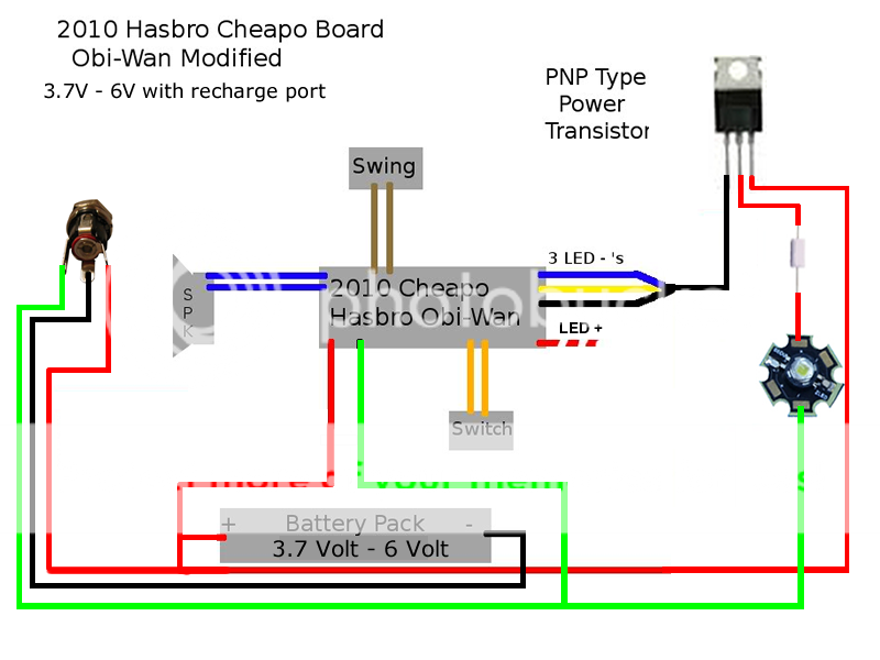
Bookmarks