cant wait for them and thanks alot!!!


cant wait for them and thanks alot!!!
Ok,
Here is a video of what the flicker looks like....
http://www.youtube.com/watch?v=iNVXWGCZfqw
Got a Question? There's a thread for that...
~Do what you can, with what you have, where you are.~Teddy Roosevelt
SollusVir everywhere else... FXsabers, Youtube, etc...

Thanks for the video Cardcollector. That looks the same as what I got with mine, except mine is green. I haven't had a chance to run out and pick up some extra parts for experimenting yet, but I'm hoping there's a simple way to tweak the brightness. I have some ideas, but my electronics knowledge is kinda lacking. It won't stop me from trying though
We all have to start somewhere. The journey is all the more impressive by our humble beginnings.
http://led.linear1.org/1led.wiz for the lazy man's resistor calculator!
http://forums.thecustomsabershop.com...e-to-Ohm-s-Law for getting resistor values the right way!
Since the problem with brightness seems to be mainly caused by dips in the current running to the speaker, I wonder if those dips could be smoothed out with a capacitor. A lot of Force FX battery/speaker have capacitors to (apparently) prevent extremely brief interruptions in power from causing the saber to not function properly.
There's always a bigger fish.

Great progress guys! I'm looking forward to a final solution on this. I just pulled a obi board for a project, so perfect timing!
Yub Yub Commander.

Does that create the same dimness issue?Originally Posted by J-Saber33

I am a bit stuck. I have my board wired up with a 5v regulator, an accent led, and a 700ma puck. I have checked and double checked that my TIP42 is wired up correctly. However when the batteries are in, the main and accent LED light up. They respond to the board being turned on by flickering appropriately, like the transistor is still pushing through the changes that cause the stock LEDs to flicker. I am stuck. Any ideas?


Which of the wiring diagrams are you using, and if you can, post pictures of your wiring.
Click here to learn all about me!
The Shoutbox: The only place you can double post!
Anybody who spells it Lightsabre is dyslexic
"Yeah, if I had Skotts face I'd hit it too" ~ Fenderbender
"You didn't buy a toy saber just to break it. You bought an economy sound card with a really complicated wrapping scheme." ~ Silver Serpent

Ok I am a little unsure of the proper resistor for my build I am using the Obi board with the recharge port setup and 7.4 battery pack and am using a P4 green I checked and the resistor that I came up with is a 10w 4.7 resistor ...I am using this diagram here ...just need some verification if my calculations are correct....thanx
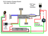
Last edited by jin starkiller; 06-22-2011 at 11:09 AM. Reason: wrong diagram ...fixed now

Try not. Do or do not, there is no try.... Yoda
CLICK HERE FOR ALL YOUR ECONO SOUND BOARD WIRING DIAGRAM NEEDS!
THREAD INDEX
LDM's Basic Saber-build Step-by-Step Tutorial


Here are the results I have gotten. With the speaker - going to the transistor base and wiring the rest of the transistor as usual I am only getting 2 V @ 100mA to the LED. So the problem is not only with the current but with the voltage as well. The speaker output is 3V at a low current and when you try to power a LED or transistor with it the LED draws 2V and the speaker drops down to 1V. There are voltage boosters out there but most of them need at least 5Volts to work with. For now we are just not getting enough power off of the speaker output to power a LED bright enough to make a decent blade. To make this usable we need to output at least 3Volts @ 1000mA, preferably 1200mA. I haven't given up yet and am still working on a solution using discrete hardware. I know it can be done using a PIC controller but most people don't have access to the equipment needed to program and download the PIC controller.
 Posting Permissions

 Reply With Quote


Bookmarks