Thanks cardcollector. I am just trying to help. I don't like to give up on anything. Thank you for creating and updating this thread.


Thanks cardcollector. I am just trying to help. I don't like to give up on anything. Thank you for creating and updating this thread.

I haven't been following this thread and my head hurts right now so I am not gonna catch up but why was people hooking the emitter up to the LED?
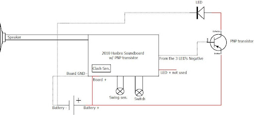
In my design (matt's diagram) I have the collector going to the LED.
I am not sure what I am missing here but I have been getting high current readings from the get go with my set up.
so please catch me up here. Did someone have a problem with my transistor I posted and if so what was it. The two I did are still going strong and are very bright with only one 3.7 Li Ion battery.
MH on FX-Forums

Thank you Rhyen!!!!! And zook is right. Its just that the transistor zook used looked like it only had two legs. So probably everyone assumed the output to the led is the emmitter. I mean what do you think of when you think emmit? Out right?
Last edited by dj2rbo; 06-22-2010 at 02:34 PM.
Originally Posted by Zook

I think most people have been looking at the diagram right above yours. It has the collector going to the batteries and the emitter going to the LED. I know that is the one I was using. The problem is when people look at this thread they scroll down to they see the first diagram with the transistor and use it. Plus for yours it says here is another way instead of here is the correct way. LOL Plus, it kinda seems logical for the collector to collect the power and the emitter to send out the power, but as we all see now, that is wrong for this application. We need to have all diagrams that use the transistor set up have the emitter going to the battery and the collector going to the LED. Thanks for all your help Zook.
yeah my trans can be confusing because it does have two long legs and one stubby one.
The stubby one and the back side of this particular transistor is the collector. I don't use the stubby leg but solder it to the back of the transistor.
I didn't mean anything negative by my post so I hope no one took it that way. I just thought maybe someone had a problem with my set up since I remember Matt saying he was ordering some transistors like mine but saw him using a different transistor.
MH on FX-Forums
I didn't think you meant anything negative at all. Most of us didn't even get to your diagram because of the one above yours. I just noticed in your diagram that you have the emitter of the transistor hooked up to the board LED +. Does the Battery + feed straight through the card?
I cleaned up the first post. I'll post the correct diagram here too.
Got a Question? There's a thread for that...
~Do what you can, with what you have, where you are.~Teddy Roosevelt
SollusVir everywhere else... FXsabers, Youtube, etc...
its close but when I posted that in the other tread I think I mentioned I jumped the + wire going into the board straight to the leg on the transistor. I didn't see much difference I don't think without the jumper though.
basically why I like mine so much is its less mess. When you take out the 3 LEDs (the entire little board with the 3 LEDs on it) the transistor hooks under that area the LEDs were in and solders straight to the board (because the trans is a surface mount trans and its hooked...well look at a US board and you will understand). Its really convenient and you don't have to worry about wires running to it and such.
I haven't taken the OBI apart to see how I can hook it up but its probably not as convenient.
Last edited by Zook; 06-22-2010 at 11:07 PM.
MH on FX-Forums

Okay so I used the set up in the diagram, it works. That LED may be brighter than it was with the Reed Relay. In fact it is. I checked it on the multi and the results are the same as previously mentioned in this thread.
One thing, the LED is on until you take the battery out, the board powers up with the switch. (I recall this in a similar thread, not sure wich...yet)
Here's what I have.
4.8 volts
Obi-board
P4 (green)
PnP transistor
The P4 may be a little over driven, not by much acording to the resistor chart. So, I don't think its trouble, but I do find it strange.
edit. I'm pretty sure I have a bad motivator.....uh....I mean transistor.
Last edited by Noyl Wendor; 06-22-2010 at 09:02 PM.

So with this new setup are you guys using any resistors on the main LED?
 Posting Permissions


 Reply With Quote

Bookmarks