


Hey guys, This thread will explain almost everything you need to know about the New hasbro Sabers w/DvD
2010 DarthVader breakdown and wiring guide
This video shows how to tear apart, wire up the LED traces, and compares sound to other sabers. Just so you know, The board will fit in a sinktube veeeery snugly...
Disassembly:
These sabers are extemely hard to take apart. Hasbro didn't skimp on the glue this time. I had to use a Dremel to cut it open. You can see where everything is in the video.
Wiring:
This is sad. The LEDs give off the following ma and 6V
LED 1: 7ma
LED 2: 7ma
LED 3: 7ma
All LEDs- together: 21ma (yes, I triple checked!)
BUT, all you have to do is wire in a transistor to get the proper ma to the LED.
I am very impressed with this saber's sound, especially the swings, they are much better responsively and mixed into the idle hum, you can hear that in the video...
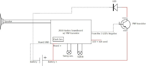
So here are some wiring Diagrams...
Just a basic circuit with a PNP type transistor.
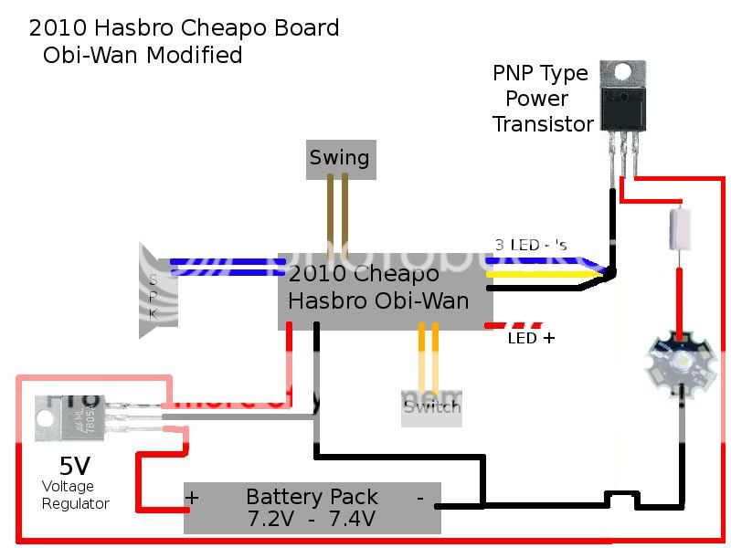
Here is one with a 5V regulator if you are using a 7.2V Li-ion setup.
Credit goes to Rhyen for finding the solution to the PNP transistor problem and the following diagrams...
7.2 V - 7.4 V with voltage regulator, recharge port and accent LED:
7.2 V - 7.4 V with voltage vegulator and accent LED (No recharge port):
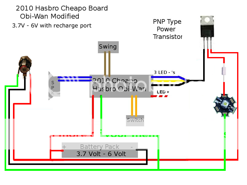
3.7 V - 6 V with recharge port and accent LED:
3.7 V - 6 V with recharge port (No accent LED):
3.7 V - 6 V Basic Set up (No recharge port or accent LED)
[/QUOTE]
Credit goes to Boj-Vaati Mau. This setup includes a buckpuck with accent LED.
Credit goes to skottsaber. This eliminates the Flash on clash and provides a nice flicker effect.
Please note that several diagrams poated throughout this thread are incorrect, they have the battery going to the collector, and the LED going to the emmitter. DO NOT wire them that way. you will only get 300-400 ma as opposed to 1000-1100ma wired as the diagrams above.


 Reply With Quote


Bookmarks