Page 6 of 8 FirstFirst ... 4 5 6 7 8 LastLast
Results 51 to 60 of 80

Thread: Clash-on-Flash without a Crystal Focus?

  1. #51

    Default "For Dummies," please

    ari-jaq, thanks for the post, but you are suddenly talking calculus while we are still trying to wrap our heads around trigonometry. I have absolutely no idea what your solutions are supposed to be doing or how we are supposed to implement them into an actual clash-on-flash saber that uses a 2010 Hasbro Electronic Lightsaber board and (possibly) a TCSS LED driver.

    To break it down to its basics:

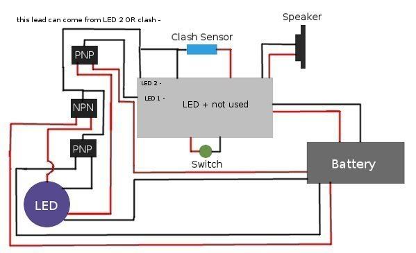
    1) One (or more?) of the LED leads in the Hasbro board is normally on, and turns off on clash. Cannibal is using a relay to reverse this, so that the LED gets power only on clash.

    2) With his current set-up, the LED chip used for clash effects is not getting enough current, and is too dim.

    It just occurred to me this morning (It's morning in Japan) that I don't see how the transistor-as-switch solution could allow us to achieve the first problem of reversing normally off to normally on.
    Last edited by Matt Thorn; 05-17-2010 at 06:17 PM.
    There's always a bigger fish.

  2. #52

    Default

    I would wire it with one switch as the normal logic gate (relay) for normal low level brightness, and throw in the second to control the extra LED/die that he wants to be normally off.

    I actually think I understand the first of ari-jaq's diagrams, and it's pretty much genius.
    It requires two gates to be saturated simultaneously (one on the positive LED lead, and one on the negative LED lead) by the intended signal wire--the one that normally goes to the relay coil; making it impossible for clash-flash to occur from surges and shorts.
    Last edited by KuroChou; 05-17-2010 at 09:23 PM.

  3. #53

    Default

    Quote Originally Posted by KuroChou View Post
    I would wire it with one switch as the normal logic gate (relay) for normal low level brightness, and throw in the second to control the extra LED/die that he wants to be normally off.

    I actually think I understand the first of ari-jaq's diagrams, and it's pretty much genius.
    It requires two gates to be saturated simultaneously (one on the positive LED lead, and one on the negative LED lead) by the intended signal wire--the one that normally goes to the relay coil; making it impossible for clash-flash to occur from surges and shorts.
    I'm definitely going to need some visual aids here. When I took a W.A.I.S. test a couple of years ago, I did great on the Perceptual Organization Index, but miserably on the Working Memory Index.
    There's always a bigger fish.

  4. #54

    Default

    I'm not totally sure on the polarity of all the wires, and the top PNP might actually need to be an NPN.
    But with this you should at least get the gist of it.


  5. #55

    Default

    Quote Originally Posted by KuroChou View Post
    I'm not totally sure on the polarity of all the wires, and the top PNP might actually need to be an NPN.
    But with this you should at least get the gist of it.

    Yay! A picture! "'[W]hat is the use of a book,' thought Alice, 'without pictures or conversations?'" None whatsoever. So I'll ask my questions using your picture:

    I have a feeling the seemingly "mis-wired" NPN in the middle has something to do with the first of ari-jaq's diagrams, but since I still don't understand that one, I'm still at sea. Though I think I see a shore on the horizon.
    There's always a bigger fish.

  6. #56

    Default

    You're correct on all accounts except the middle transistor.
    I think that's the way you would incorporate ari-jaq's schematic, but it may be reversed (it would have to do with polarity, and since I'm not 100% on ANY of the wires here, it's certainly subject to misuse).
    In all honesty the transistor in question isn't even necessary to make it function, just makes it more reliable in the sense that it makes false clashes impossible.

  7. #57
    Jedi Knight cannibal869's Avatar
    Join Date
    Sep 2008
    Location
    Home of NUCLEAR JEDI SABERS
    Posts
    1,027

    Default

    Quote Originally Posted by Matt Thorn View Post
    Yay! A picture! "'[W]hat is the use of a book,' thought Alice, 'without pictures or conversations?'" None whatsoever. So I'll ask my questions using your picture:

    I have a feeling the seemingly "mis-wired" NPN in the middle has something to do with the first of ari-jaq's diagrams, but since I still don't understand that one, I'm still at sea. Though I think I see a shore on the horizon.
    I'm with Matt on this one.

    I think that if the circuit labeled as LED 2- is actually coming from the CLASH sensor, then yes, I think this is feasible... but it can NOT come from the normal LED 2- from the board. Also, if I'm looking at this correctly, there should actually be a black wire coming from the middle NPN transistor to the board, and the two black wires attaching to the bottom of the lower PNP transistor should actually be red positive wires.

    I'm not entirely sure you can wire it to the clash sensor either although I suppose there's really only one way to tell...

    I ordered some parts from mouser already - will test out some stuff and post up results if there's anything useful.
    LOCKHEED

  8. #58

    Default

    When using transistors as switches, they only have one trigger pin, where relays would have two in order to activate the solenoid coil.
    Technically, the center pin would share polarity with one of the outer pins, and the extra would be opposite;
    but for the sake of following what was going on on the LED, I colored the wires so you could see which transistor was controlling the positive pad and which was controlling the negative pad.

    Follow the leads from the battery to the lower two transistors;
    the whole point of having two of them is to interrupt the clash LED circuit on both the positive, AND negative sides, and needing to activate both of them at the same time in order to complete.
    That's why their center pins are tied together, and then to wherever you're taking your clash signal from--be that straight from the sensor, or from the extra LED pad.

  9. #59

    Default

    There's always a bigger fish.

  10. #60

    Default


    In any case, this was for illustrative purposes only, and I'm interested in being schooled by someone with a much better understanding of all this than myself....

Bookmarks

Posting Permissions

  • You may not post new threads
  • You may not post replies
  • You may not post attachments
  • You may not edit your posts
  •