Page 5 of 8 FirstFirst ... 3 4 5 6 7 ... LastLast
Results 41 to 50 of 80

Thread: Clash-on-Flash without a Crystal Focus?

  1. #41
    Jedi Knight cannibal869's Avatar
    Join Date
    Sep 2008
    Location
    Home of NUCLEAR JEDI SABERS
    Posts
    1,027

    Wink

    Quote Originally Posted by Matt Thorn View Post
    Cannibal, a TIP120 NPN transistor has a peak DC collector current of a whopping 5 amperes. It's about the size and shape of a standard 5V voltage regulator. If you need a smaller package, the BC63916 (at 1 ampere) is the most powerful one I know of in the TO-92 package.

    And, yeah, it looks like you have the NPN wired wrong. As the name implies, it's Negative-Positive-Negative, so the leads on both sides should be negative, and the lead in the middle should be positive.

    For a high-output PNP, you could try a KSA940 (1.5 A) or a BD242 (3A).

    As for the second diagram, you're not planning on two separate battery packs, are you? Two 14500 li-ions is more than enough to run the whole thing. You would just wire them in parallel, and put a 5V voltage regulator between the battery pack and the Hasbro board.

    P.S.: That's a bummer about Eandori, J-Lo. I have great respect for him. I hope he'll find his way back here eventually.
    See? I knew there was someone around here who had better electronics knowledge LOL...

    Actually, I literally just learned about Darlington Transistors yesterday (basically two NPNs hooked up together). Thanks for the link Matt - very helpful. And as for the wiring, you actually have to look at the orientation of the leads - the positive in this case should be going to the Base (I believe), and the Collector and Emitter should be hooked up to the negative input and output. The way I understand it is that the positive layer (base) is wedged between the negatives in an NPN (so yes you are correct about that), and acts sort of like a gate? So when the positive input is on, this allows the negative signal to pass through and get amplified???

    I'll try ordering some more parts and doing some more experimenting this week. We have an outdoor engagement photoshoot tomorrow, so probably limited saber time...

    -C
    LOCKHEED

  2. #42

    Default

    If you're going to be using high power transistors, you can skip the relay altogether, and wire up a transistor switch.
    It'll have a faster switch speed that way anyway.

  3. #43
    Jedi Knight cannibal869's Avatar
    Join Date
    Sep 2008
    Location
    Home of NUCLEAR JEDI SABERS
    Posts
    1,027

    Default

    Quote Originally Posted by KuroChou View Post
    If you're going to be using high power transistors, you can skip the relay altogether, and wire up a transistor switch.
    It'll have a faster switch speed that way anyway.
    Huh? Transistor switch?

    The purpose of the relay (DPDT or DPST) was to hook up power going to the clash LED through the normally closed circuit in order to get the LED to turn on when the clash was activated. Does a transistor switch have the same function? I don't even know what a transistor switch is, so you'll have to enlighten me Then again, I didn't even know about the existence of PNP or NPN transistors until about 2 weeks ago!

    -C
    LOCKHEED

  4. #44

    Default

    http://www.rason.org/Projects/transwit/transwit.htm

    While transistors have many uses, one of the less known uses by amateurs is the ability for bipolar transistors to turn things on and off. While there are limitations as to what we can switch on and off, transistor switches offer lower cost and substantial reliability over conventional mechanical relays. In this article, we will review the basic principles for transistor switches using common bipolar transistors.

    The most commonly used transistor switch is the PNP variety shown in Figure 1. The secret to making a transistor switch work properly is to get the transistor in a saturation state...

  5. #45

    Default

    Here are some more useful links.
    http://www.kpsec.freeuk.com/trancirc.htm
    http://www.electronics-tutorials.ws/...or/tran_4.html
    http://www.allaboutcircuits.com/vol_3/chpt_4/2.html
    http://techhouse.brown.edu/~dmorris/projects/tutorials/transistor.switches.pdf
    http://www.mayothi.com/transistors.html

    The idea is that the transistor won't start working its amplification magic until it gets a sufficient amount of power. So that would solve your problem of the LED staying on while the board is off.

    I think.

    I haven't tried to use a transistor as a switch myself, but I knew that it could serve that function.

    I keep trying to force myself to learn more about electronics, but the widely-respected book I bought (Teach Yourself Electricity and Electronics, Fourth Edition, by Stan Gibilisco) is like Ambien. I strongly recommend it for insomnia. It may be great if you're looking to start a career as an electrician or electrical engineer, but it's downright painful for a hobbyist like me who simply wants to know how to solve the problems at hand. I'm waiting for my copy of Electronics For Dummies to arrive. Yes! I'm a dummy! And I'll put up with the wretched "humor" common to the whole "_____ for Dummies" series if it will help me to get from point A to point B.
    Last edited by Matt Thorn; 05-17-2010 at 02:00 AM.
    There's always a bigger fish.

  6. #46

    Default

    With nearly all the commercial boards being low voltage based (3-6v) like the MR and hasbro's I prefer to use logic level MOSFET transistors.

    Their input to the gate pin is desgned to be driven by the common output levels of logic circuits which means getting to their operating saturation voltage is much easier. They also tend to have very low On resistances so are almost the perfect switch.

    Ive never figured out why people used the relay method in the first place. The point of a relay is to handle current loads beyond what silicon can do (or switch multiple seperate circuits).
    The MR boards with their 6 transistors are basically driving the relays coil which is moving the physical contacts of the relays 'switch'. For the power levels we use in a sabre its just as easy to wire up a MOSFET driven be the same source as the transistors but rated for a higher power. In effect the MOSFET is acting just like a relay but with no moving parts and alot smaller physical size.

    I prefer to use NPN ones and just put them between the load (led) and ground which is how the MR boards are done anyway.
    Ive used some ZVN4310a to drive high current leds, they are rated for about 1A continuous and for brief pulses at a whopping 15A (max) so could be used for a flash on clash. Best thing is they are the small T0-92 form factor so are the same size as the ones that come on the MR boards (not sure if they are identical pin outs though as I usually wire them on a small jumper board).

    If you want higher currents though theres loads out there, just remember to look for a logic level version. Something like the NTE2980 which has over 7amps continuous and 31 amps pulsed (but is the larger T0-220 style case).
    Phil Higgins


  7. #47

    Default

    Neophyl, now that you've betrayed your degree of knowledge, you must realize we'll never let leave this thread.

    Could you find a few minutes to doodle a diagram showing us how you would wire this, including the battery setup? Until you showed up, we've been the blind leading the blind here.
    There's always a bigger fish.

  8. #48

    Default

    I know I've tossed the transistor vs relay argument around a few times and never gotten a response.
    It's good to know more than one or two other people actually do this.

  9. #49
    Jedi Knight cannibal869's Avatar
    Join Date
    Sep 2008
    Location
    Home of NUCLEAR JEDI SABERS
    Posts
    1,027

    Default

    See? I knew there were people around here who would take one look and come up with a better solution...

    I'm gonna go make some popcorn and wait for a better schematic
    LOCKHEED

  10. #50

    Default

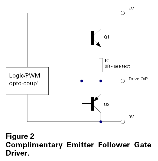
    I don't know if this helps or not but I found this on another site as to how to build a mosfet driver.

    You can just use a gate driver IC. THat's the simplest and most compact solution. Or you can build one discretely.

    THe simplest discrete solution is a high-side NPN BJT and a low-side PNP transistor (yes, that's right the NPN Is on the high-side and the PNP is on the low-side. This means that the transistor gradually turns off as the power MOSFET gate capacitance becomes charged and helps to prevent shoot-through currents in the gate driver).


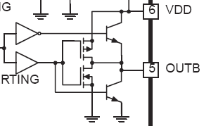
    A more advanced solution is to use BJTs and MOSFETs in parallel:

    In this example they use two NPN BJTs, but you could instead replace that with a high-side NPN and low-side PNP just like the previous example (and you can remove the inverters as well if you do that).

    The BJTs turn on very quickly and provide the high current pulse needed to charge or discharge the power MOSFET gate capacitance. But they can't bring the capacitance close to the rails of the gate drive supply voltage. THe MOSFETs turn on slower but can pull the gate capacitance very close to the rail voltage.

    Hokey religions and ancient weapons are no match for a good blaster at your side, kid.

Bookmarks

Posting Permissions

  • You may not post new threads
  • You may not post replies
  • You may not post attachments
  • You may not edit your posts
  •